SG
1 /42Pages

SG
1 /42Pages
Catalog excerpts

Directional spool valve type SG and SP Product documentation Single valve for pipe connection or manifold mounting Operating pressure pmax: Flow rate Qmax:
Open the catalog to page 1
© by HAWE Hydraulik SE. The reproduction and distribution of this document as well as the use and communication of its contents to others without explicit authorization is prohibited. Offenders will be held liable for the payment of damages. All rights reserved in the event of patent or utility model applications. Brand names, product names and trademarks are not specifically indicated. In particular with regard to registered and protected names and trademarks, usage is subject to legal provisions. HAWE Hydraulik respects these legal provisions in all cases. HAWE Hydraulik cannot provide individual...
Open the catalog to page 2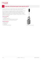
Overview of directional spool valves type SG and SP Directional spool valves are a type of directional valve. They control the direction of movement and the velocity of single and double-acting hydraulic consumers. The directional spool valve type SG is available as a single valve for pipe connection. Type SP is available as a manifold mounting valve. Due to its robust design, operating pressures up to 400 bar are achievable. They are exible in use and are available with various different circuit symbols and types of actuation. Intended applications include mobile hydraulics, in particular in...
Open the catalog to page 4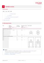
Available versions 2.4 "Actuation" 2.3 "Pressure-limiting valve (only type SG)" 2.2 "Circuit symbol" 2.1 "Basic type and size" 2.1 Basic type and size Type Flow rate Qmax (lpm) R Pressure pmax (bar) at port P, A, B Circuit symbol Single valve for pipe connection SG 0 Single valve for manifold mounting SP 1 DAMAGE * Ports for a single valve for manifold mounting see Chapter 4.2, "Single valve for manifold mounting, type SP" ** The maximum return pressure is dependent on the pressure-limiting valve and actuation. see Chapter 2.3, "Pressure-limiting valve (only type SG)" see Chapter 2.4.1, "Manual...
Open the catalog to page 5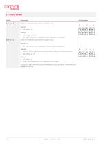
2.2 Circuit symbol Coding Circuit symbol 4/3 or 3/3 directional spool valve for parallel circuit G Only for size 1, 2, 3, 5 With SG 1 not for use in conjunction with a pressure-limiting valve 4/2 or 3/2 directional spool valve for parallel circuit Coding R, V: ■ With SG 1 not for use in conjunction with a pressure-limiting valve Negative overlap (slight oating position between the two switching positions) Only for size 2, 3, 5 Only for size 2 Not for use in conjunction with a pressure-limiting valve For coding V and Q the port R must be connected to the tank in order to drain away the leakage...
Open the catalog to page 6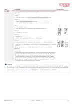
Circuit symbol 4/3 or 3/3 directional spool valve for series or parallel circuit. Not for use in conjunction with a pressure-limiting valve in a series circuit. Coding L: ■ With SG 0 and SG 5 not for use in conjunction with a pressure-limiting valve Special version to avoid decompression surges Only for SG 5, not for use in conjunction with a pressure-limiting valve L LS Only for size 0, 1, 2, 3 With SG 0 not for use in conjunction with a pressure-limiting valve Only for SG 3 Not for use in conjunction with a pressure-limiting valve Only possible for SG 2 in conjunction with a pressure-limiting...
Open the catalog to page 7
2.3 Pressure-limiting valve (only type SG) Coding Without coding Without pressure-limiting valve Pressure-limiting valve for SG 0, 1 Zinc die-cast spring housing, pmax at port R = 20 bar ■ ■ Circuit symbol - Pressure-limiting valve for SG 2, 3, 5 Zinc die-cast spring housing, pmax at port R = 20 bar ■ ■ Pressure-limiting valve for SG 2, 3, 5 Steel spring housing pmax at port R > 20 bar (proof against pressure surges to 300 bar) ■ ■ Special version for special installations and marine applications DAMAGE The pressure in R is additional to the pressure setting. DAMAGE The version with the pressure-limiting...
Open the catalog to page 8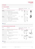
2.4 Actuation 2.4.1 Manual actuation Coding Manual operation with spring return ■ ■ Circuit symbol AK: Standard version AKS: Special version with a corrosion-resistant steel shaft. Especially for maritime applications. For size 2, 3, 5 the lever housing has an additional at grease nipple. Actuation supplement 1: without hand lever CK, CKS CK1, CKS1 Manual operation with 3-stage detent ■ ■ CK: Standard version CKS: Special version with a corrosion-resistant steel shaft. Especially for maritime applications. For size 2, 3, 5 the lever housing has an additional at grease nipple. Actuation supplement...
Open the catalog to page 9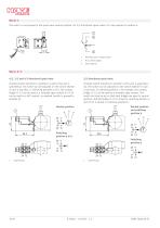
Size 0, 1 The switch is not pressed in the spool valve neutral position, for 3/3 directional spool valves it is also pressed in position a. Normally open contact (blue) N/C contact (grey) Input (black) 3/3 directional spool valve (Contact switch functions in positions a and b) The cam is symmetrical. The switch can be adjusted on the switch retainer in such a way that, in switching positions a or b, the contact bridge 11-12 can be used as a normally open contact or 23-24 can be used as a N/C contact, as required (switch is pressed in position 0). (Contact switch functions in position a) The cam...
Open the catalog to page 10
2.4.3 Mechanical actuation Coding Circuit symbol Roller head actuation – Only for parallel circuit – Only for 4/2 or 3/2 directional spool valve Ball head actuation ■ – Only for size 2, 3 and 5 – Only for parallel circuit – Only for 4/2 or 3/2 directional spool valve Roller head actuation: For lateral actuation by a cam or a control rod, a hardened plunger must have a roller bearing roller at its outer end. The plunger is installed in a ange housing with anti-twist protection, and is tted with a strong return spring. Ball head actuation: For the axial direction of actuation the outer end is...
Open the catalog to page 11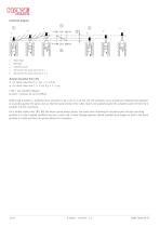
Actuation diagram Roller head Ball head Switching travel Spring force for spool valve size 0, 1 Spring force for spool valve size 2, 3, 5 Overall actuation force (N) for spool valve size 0, 1: Fges = F + 2.8 pR for spool valve size 2, 3, 5 (4): Fges = F + 5 pR F (N) = see actuation diagram pR (bar) = pressure at port R (reux) Roller head actuation is preferred when actuation is by a cam or a control rod. The actuation curve should be congured and adjusted at assembly against the spool valve so that the spool stroke of the roller head is not pushed beyond the actuation path (3) from the 0 position...
Open the catalog to page 12All HAWE Hydraulik SE catalogs and technical brochures
 Pressure switch type DG 2025
21 Pages
 VR
VR15 Pages
 BVE
BVE54 Pages
 SLC
SLC17 Pages
 BNG
BNG25 Pages
 BA
BA45 Pages
 VB
VB88 Pages
 VP
VP35 Pages
 VH
VH6 Pages
 SL1
SL115 Pages
 ROLV
ROLV23 Pages
 EM
EM41 Pages
 PS
PS20 Pages
 K60N
K60N19 Pages
 V30D
V30D60 Pages
 V80M
V80M30 Pages
 V30E
V30E51 Pages
 RZ
RZ12 Pages
 Radial piston pump type R, RG
23 Pages
 C40V
C40V47 Pages
 Mini hydraulic power pack type A
23 Pages
 HR 080
17 Pages
 HICON
HICON14 Pages
 INKA
INKA35 Pages
 FXU
FXU35 Pages
 V60N
V60N71 Pages
 Product catalogue
299 Pages


