RZ
1 /12Pages

RZ
1 /12Pages
Catalog excerpts
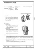
Dual stage pumps type RZ High pressure pump Pressure pmax HP Delivery flow Qmax HP Geo. displacement Vgeo HP Low pressure pump Pressure pmax LP Delivery flow Qmax LP Geo. displacement Vgeo LP See also: Hydraulic power packs type RZ High pressure pump prepared for retrofitting of a gear pump Dual stage pumps type RZ consist of a high pressure section, i.e. a radial piston pump acc. to D 6010, and a directly mounted, play compensated gear pump forming the low pressure section. The housing of the high pressure pump provides a flange where the low pressure pump can be directly mounted. The drive shaft is designed as a thru-shaft to drive the second pump. High / Low pressure pump combination o Dual stage pumps Use for press controls where rapid traverse and working speed is required. The low pressure flow is usually fed into a common line via a pressure actuated idle circulation valve which switches over as soon as the pre-set pressure is exceeded i.e. automatic by-pass. o Dual circuit pumps These pumps are used for dual circuits where two individual circuits are fed simultaneously but pressure independent. Possible delivery flows and pressure depend on the combination. The two delivery flows are controlled via directional valves enabling idle circulation at one switching position. Pump installation o Installation outside of the tank The pumps are mounted to the electric motor (design IM B 35) via bell-housing and flex-coupling outside the tank. Best installation is beneath or below the tank with the suction line steadily declining. This ensures that the pump is automatically bled and helps suction, even when the fluid level is at minimum (see also sect. 5). There is a wide range of bell-housings and flex-couplings available, see D 6010 Z for order codings. o Installation in the tank The most common installation is with the electric motor (design IM B 5 or IM V1) vertically on the cover plate and bell-housing, flex-coupling, and pump inside the tank. The order codings of the utilized bell-housings, flex-couplings are listed in D 6010 H. The respective suction parts are listed in D 6010 Z. These can be combined with pipe elbows conforming DIN 2950, shape D 4 or A 4. HAWE Hydraulik SE STREITFELDSTR. 25 • 81673 MÜNCHEN © 1974 by HAWE Hydraulik Dual stage pumps RZ April 2000
Open the catalog to page 1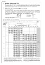
Available versions, main data The pressure specified in the tables below represent the maximum recommended values with which the respective high-pressure or low-pressure sections (pHPmax or pLPmax) can be loaded, with respect to the design of the units (pump cylinder or gear pump). The permissible pressure for a specific application have to be limited at a lower level in accordance with the power distribution. See also sect. 4 „Power demand“! High pressure pump prepared for retrofitting of a gear pump For main data see also D 6010. The high-pressure pump (HP stage) is individually available....
Open the catalog to page 2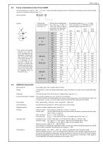
Coding high pressure section from sect. 2.1 Delivery flow coding (guide line value QHP in lpm at 1450 rpm) second figure represents the geometric displacement in cm3/rev. Permissible pressure pLP max 1) in (bar) when mounted to a HP-pump of the specified design (see also sect. 2.1) 6911 6914 7631 6910 6912 6916 actual permissible pressure pLP may be lower, depending on the application. Observe the max. drive power rating of the shaft, see sect. 4. It is advisable for an economic bearing service life to restrict the middled operating pressure of subsequent load cycles (e.g. accumulator charging)...
Open the catalog to page 3
Mass (weight) approx. (kg) Design Suited for low pressure stage High pressure stage Coding acc. to sect. 2.2 Low pressure stage Attention: The individual weights of HP- and LP-pump have to be added with pump combinations acc. to sect. 2.2 Power demand The required power depends on the type of application. It is important that the total power requirement does not exceed the permissible power rating for the shaft (Prequ. $ Pmax), when calculating the necessary drive power Prequ. for the pump combination at the respective load. HP-pump max. power rating Pmax (kW) The specific power kHP, kLP is limited...
Open the catalog to page 4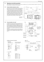
Bleeding and initial operation When starting up the pump for the first time and whenever changing the oil in the system, bleeding is necessary. This prevents intake problems or air being fed to the consumers. Pumps installed outside the oil tank Slacken (but do not remove) the bleeder screw after filling the oil tank and wait until oil comes out. Then tighten the bleeder and allow pump (HP- and LP-pressure stage) to run briefly without pressure (assuming the control system provides this possibility). Otherwise set back the pressure limiting valve to zero pressure and run the pump. Then run the...
Open the catalog to page 5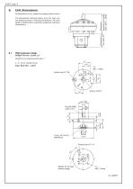
Unit dimensions All dimensions in mm, subject to change without notice! Dimension H from sect. 6.2 The dimensional drawings below show the high and low pressure pumps in individual illustrations. The total length is determined by adding the respective individual dimensions.s High pressure stage Design 7631 acc. to sect. 2.1 Suited for low pressure pump size /1 2-, 3-, and 5-cylinder pump Type RZ 0,18/1 ... 2,27/1 4x M6, 11 deep Suction port G* 3/8 Bleeder for the high pressure stage
Open the catalog to page 6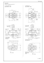
D 6910 page 7 Design 6910 Suited for low pressure pump size /2 3-cylinder pump Type RZ 0,9/2 ... 6,5/2 Counter sinking for O-ring 36x2 NBR 90 Sh Bleeder for the high pressure stage Pressure port P G* 1/4 Counter sinking for O-ring 36x2 NBR 90 Sh Bleeder for the high pressure stage
Open the catalog to page 7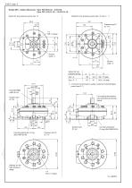
D 6910 page 8 Design 6911, single radial pump Type RZ 0,9/3 (/4) ... 6,5/3 (/4) Type RZ 1,4/2 (/3, /4) ... 15,3/2 (/3, /4) Suited for low pressure pump size /3 and /4 Suited for low pressure pump size /2 Pressure port P G* 1/4 4x M8, 13 deep Suited for low pressure pump /4 only for mounting of a suited, customer furnished gear pump (sect 2.1) Key DIN 6888, width 6 mm For missing dimensions, see dimensional drawing below ! Suction port G* 3/4 Counter sinking for O-ring 36x2 NBR 90 Sh Bleeder for the high pressure stage Counter sinking for O-ring 50x2 NBR 90 Sh
Open the catalog to page 8All HAWE Hydraulik SE catalogs and technical brochures
 Pressure switch type DG 2025
21 Pages
 VR
VR15 Pages
 BVE
BVE54 Pages
 SLC
SLC17 Pages
 BNG
BNG25 Pages
 BA
BA45 Pages
 VB
VB88 Pages
 VP
VP35 Pages
 VH
VH6 Pages
 SL1
SL115 Pages
 ROLV
ROLV23 Pages
 EM
EM41 Pages
 PS
PS20 Pages
 K60N
K60N19 Pages
 V30D
V30D60 Pages
 V80M
V80M30 Pages
 V30E
V30E51 Pages
 Radial piston pump type R, RG
23 Pages
 C40V
C40V47 Pages
 Mini hydraulic power pack type A
23 Pages
 HR 080
17 Pages
 HICON
HICON14 Pages
 INKA
INKA35 Pages
 FXU
FXU35 Pages
 V60N
V60N71 Pages
 Product catalogue
299 Pages


