ROLV
1 /23Pages

ROLV
1 /23Pages
Catalog excerpts

Directional seated valve type ROLV Product documentation Operating pressure pmax: Flow rate Qmax:
Open the catalog to page 1
© by HAWE Hydraulik SE. The reproduction and distribution of this document as well as the use and communication of its contents to others without explicit authorization is prohibited. Offenders will be held liable for the payment of damages. All rights reserved in the event of patent or utility model applications. Brand names, product names and trademarks are not specifically indicated. In particular with regard to registered and protected names and trademarks, usage is subject to legal provisions. HAWE Hydraulik respects these legal provisions in all cases. HAWE Hydraulik cannot provide individual...
Open the catalog to page 2
Overview of directional seated valve type ROLV Directional seated valves are a type of directional valve. As cone valves they are tightly sealed, with zero leakage in the closed state. The directional seated valve type ROLV is available as a 3/2, 4/2 or 4/3-way directional seated valve with different plug types. The patented assembly consists of two parts: a round basic valve with the valve inserts, and an adapter plate which can be designed for manifold mounting with nominal size NG 6 as the standard connection pattern, or for direct pipe connection. Additional elements such as a check valve,...
Open the catalog to page 4
Available versions Ordering examples ROLV 14 ROLV 14 ROLV 14 2.7 "Actuating solenoid" 2.6 "Additional elements at T" 2.5 "Additional elements at port A and/or B" 2.4 "Additional elements at port P" 2.3 "Single connection block" 2.2 "Circuit symbol" 2.1 "Basic type and size" 2.1 Basic type and size Type Flow rate Qmax (l/min) Directional seated valve 2.2 Circuit symbol Coding Circuit symbol
Open the catalog to page 5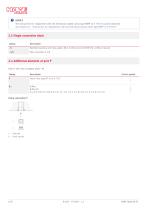
NOTICE The instructions for replacement with the directional seated valves type NBVP to D 7765 N must be observed see Chapter 6.1, "Instructions for replacement with the directional seated valves type NBVP to D 7765 N" 2.3 Single connection block Coding Manifold mounting with hole pattern NG 6 to ISO 4401-03 (CETOP 03) or DIN 24 340-A6 2.4 Additional elements at port P Only in the case of adapter plate - N Coding Circuit symbol Check valve type ER 13 to D 7325 Orice B Check valve R HAWE Hydraulik
Open the catalog to page 6
2.5 Additional elements at port A and/or B Only adapter plate - N Coding Circuit symbol Restrictor check valve type EBR 14 to SK 7966 300 in A and/or B to restrict consumers Orice-#: 0.6; 0.7; 0.8; 0.9; 1.0; 1.2; 1.5; 2.0 Restrictor check valve type EBR 14 to SK 7966 300 in A and/or B to open consumers Orice-#: 0.6; 0.7; 0.8; 0.9; 1.0; 1.2; 1.5; 2.0 Orice Restrictor check valves (installation position observed!)
Open the catalog to page 7
2.6 Additional elements at T Only in the case of adapter plate - N Coding Return pressure stop (check valve) type ER 14 to D 7325 Circuit symbol Return pressure stop S. 2.7 Actuating solenoid Coding Electrical connection Coding G with line connector Coding L with LED plug Coding WG with rectifier in the line connector Coding 5K with cast-on cable 5 m long NOTICE The specifications regarding the IP protection class apply for versions featuring a properly assembled male connector. Connection pattern G .., X .., L .. (WG ..) HAWE Hydraul
Open the catalog to page 8
Without coding Series (TPU, NBR) Additional seal variants available on request
Open the catalog to page 9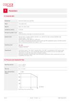
3.1 General data Designation Directional seated valve type ROLV Cone-seated valve Steel, zinc-nickel coated Installation position Negative. During switching, all passages are connected to each other. Hydraulic uid Hydraulic uid, according to DIN 51 524 Parts 1 to 3; ISO VG 10 to 68 according to DIN ISO 3448 Viscosity range: 4 - 800 mm2/s Optimal operating range: approx. 10 - 500 mm2/s Also suitable for biologically degradable hydraulic uids type HEPG (polyalkylene glycol) and HEES (synthetic ester) at operating temperatures up to approx. +70°C. Cleanliness level Environment: approx. -40 to...
Open the catalog to page 10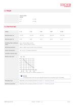
3.3 Weight Circuit symbol Coding G, D 3.4 Electrical data Coding Switching times (reference value) I100% < 60 ms (direct current) ED100% < 200 ms (direct current) Switching operations Approx. 2000/h approximately evenly distributed Contact temperature Insulation material class Relative duty cycle %ED-5 min rel. duty cycle; TU ambient temperature (°C) NOTICE The thermal load of the coil can be reduced by means of an economy circuit, for example. Protection class Depending on the actuating solenoid see Chapter 2.7, "Actuating solenoid" Electrical connection Depending on the actuating solenoid see...
Open the catalog to page 11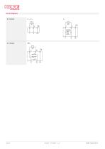
Circuit diagrams DC voltage
Open the catalog to page 12
3.5 Characteristic lines Viscosity of the hydraulic uid approx. 60 mm2/s Dynamic pressure characteristic curve ROLV 14 G ROLV 14 W, ROLV 14 D, ROLV 14 Z Additional orices
Open the catalog to page 13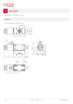
All dimensions in mm, subject to change. 4.1 Valve Circuit symbol W, Z with adapter plate - N Solenoid turned in any direction
Open the catalog to page 14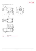
Circuit symbol W, Z with adapter plate - 3/8" Solenoid turned in any direction
Open the catalog to page 15
Circuit symbol G, D with adapter plate - N Solenoid turned in any direction
Open the catalog to page 16
Circuit symbol G, D with adapter plate - 3/8" Solenoid turned in any direction
Open the catalog to page 17
4.2 Hole pattern of the base plate Base plate hole pattern for adapter plate - N as per ISO 4401-03 (CETOP 03) 4.3 Actuating elements Electrical actuation Coding X
Open the catalog to page 18
Manual override To actuate the valve: Use a steel pin or screwdriver etc. to depress the brass bolt (visible on the upper face). NOTICE The pressure at port T generates a load on the brass bolt acting on the area of # 3 mm; at 50 bar this is approx. 40 N! 1 Auxiliary tool for actuation (do not use any parts with sharp edges)
Open the catalog to page 19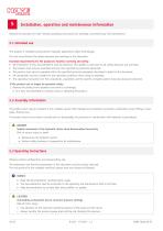
Installation, operation and maintenance information Observe the document B 5488 “General operating instructions for assembly, commissioning, and maintenance.” 5.1 Intended use This product is intended exclusively for hydraulic applications (uid technology). The user must observe the safety measures and warnings in this document. Essential requirements for the product to function correctly and safely: All information in this documentation must be observed. This applies in particular to all safety measures and warnings. The product must only be assembled and put into operation by specialist personnel....
Open the catalog to page 20All HAWE Hydraulik SE catalogs and technical brochures
 Pressure switch type DG 2025
21 Pages
 VR
VR15 Pages
 BVE
BVE54 Pages
 SLC
SLC17 Pages
 BNG
BNG25 Pages
 BA
BA45 Pages
 VB
VB88 Pages
 VP
VP35 Pages
 VH
VH6 Pages
 SL1
SL115 Pages
 EM
EM41 Pages
 PS
PS20 Pages
 K60N
K60N19 Pages
 V30D
V30D60 Pages
 V80M
V80M30 Pages
 V30E
V30E51 Pages
 RZ
RZ12 Pages
 Radial piston pump type R, RG
23 Pages
 C40V
C40V47 Pages
 Mini hydraulic power pack type A
23 Pages
 HR 080
17 Pages
 HICON
HICON14 Pages
 INKA
INKA35 Pages
 FXU
FXU35 Pages
 V60N
V60N71 Pages
 Product catalogue
299 Pages


