PSLF
1 /60Pages

PSLF
1 /60Pages
Catalog excerpts

Proportional directional spool valve type PSLF, PSVF, and SLF according to the Load-Sensing principle size 3 and 5 (manifold mounting) 1. General information The directional spool valves types PSLF and PSVF as well as the individual sections type SLF serve to control both, the direction of movement and the load-independent, stepless velocity of the hydraulic consumers. In this way several consumers may be moved simultaneously, independently from each other at different velocity and pressure ratings, as long as the sum of the partial flows needed for this is within the total delivery supplied by the pump. The proportional spool valves of this pamphlet are designed as manifold mounting valves. They may be also combined as valve banks via the sub-plates available from HAWE. They consist of three functional groups. Basic data Design Prop. directional spool valve according to the Load-Sensing principle Versions Individual valves and valve banks (manifold mounting) Operating pressure pmax 420 bar Flow Qmax 80 (120) lpm (size 3) Qmax 160 (240) lpm (size 5) Further technical information: Size Design Manifold mounting design Valve bank design (CAN onboard) Valve bank design Valve bank design Manifold mounting design ; Inlet section(control section) < Size 5 (valve bank design) = End plate > Sub-plates HAWE Hydraulik SE STREITFELDSTR. 25 • 81673 MÜNCHEN © 1998 by HAWE Hydraulik Prop. directional spool valve PSLF, PSVF and SLF August 2011-0
Open the catalog to page 1
Type coding, overview Order examples: Valve section (for individual orders, without sub-plate) Inlet section (for individual order, without sub-plate) Valve bank Basic type coding for the valve bank or inlet section (see table 1 and 4 in sect. 3.1.1 and 3.1.2) as well as valve sections (see sect. 3.2.1) Supply with pressurized oil by means of fixed pump (open center) Supply with pressurized oil by means of variable displacement pump (closed center) with a delivery flow controller, or as a second, separate unit if both valve banks are connected to a constant pressure system Individual valve section,...
Open the catalog to page 2
Types of actuation (acc. to table 19 and 20, sect. 3.2.1) /A Manual actuation /E Electro-hydraulic actuation /EI Like /E however without stroke limitation /EA Electro-hydraulic and manual actuation /E0A Like /EA, however without actuation solenoid (prepared for retrofitting) /H, /F Hydraulic actuation /H UNF, /F UNF Like /H, /F however with port thread 7/16-20 UNF-2B SAE-4 (conf. SAE J 514) /HA, /FA Hydraulic, (solenoid) and manual actuation /HA UNF, /FA UNF Like /HA, /FA however with port thread 7/16-20 UNF-2B SAE-4 (conf. SAE J 514) /HEA, /FEA Hydraulic and electric actuation /HEA UNF, /FEA...
Open the catalog to page 3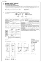
Available versions, main data Inlet section (control section) There are two basic variations of connection blocks: o Connection blocks with integrated 3-way flow controller, suitable for a fixed pump system (open-center) -type PSLF (see sect. 3.1.1) o Connection blocks suited for a variable displacement pump system (closed center), a constant pressure systems, or if a second or more separately located directional spool valve banks are fed in parallel - type PSVF (see sect. 3.1.2). PSLF A1 F/250 - 3 - G 24 PSVF A2/300 - 5 Order coding for an inlet section as individual section (examples): (Attention:...
Open the catalog to page 4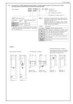
Inlet sections for variable displacement pump systems / constant pressure system or for a second and all other separately parallel connected directional spool valve banks type PSVF Order examples: (valve bank) (individual section) Nom. voltage acc. to table 10 Sub-plate acc. to table 3, sect. 3.1.1 Table 4: Basic type and size Coding and size PSVF A ..-3 PSVF A ..-5 Max. pump delivery flow (lpm) Individual section Type PSLF...-5 can be converted any time for use with variable displacement pumps (similar to type PSVF AS..-5), see sect. 6.3.3. Code letter for features within the LS-signal duct...
Open the catalog to page 5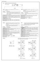
Additional elements for the inlet sections Order examples: Table 8 Table 7: Coding for control oil supply (for symbol, see sect. 3.1.1 and 3.1.2) Coding Without pressure reducing valve for actuation coding A, C or P acc. to sect. 3.2, table 18 or in the case of external control oil supply (20-40 bar) for other actuations With integrated pressure reducing valve for internal control oil supply for actuations coding H (HA, HEA, F, FA, FEA).. and E(EA).. or as pick-up for other control valves (max. permissible control oil flow approx. 2 lpm) Control pressure: Coding 1: approx. 20 bar (+ return pressure...
Open the catalog to page 6
Solenoid voltage and version Electr. connection conf. EN 175 301-803 A, via plug (MSD 3-309) Suffix: Applies only to the solenoid actuation coding E, EA, HEA, FEA (table 20) and the functional cut-off (coding F, FP, table 17), see also sect. 4.3 Actuation solenoid 3-pin (standard) Manual emergancy actuation (standard with functional cut-off F., FP., acc. to table 17) Manual emergancy actuation with pushbutton (standard with functional cut-off FPH.., FP., acc. to table 17) 4-pin actuation solenoid (only 24V DC) Electr. connection conf. EN 175 301-803 C, via plug (MSD 6-209), 4-pin actuation solenoid...
Open the catalog to page 7
End plates of valve bank Order example: PSLF A1 F100/380/6 - 5 -... - E1 - G 24 Table 11: End plates End plate External Internal port T control oil (separate return galreturn pipe lery to the tank) Description Order coding of an end plate as separate part (example): SLF 5 - E 1 SLF 3 - E 6 - G 24 (State the size: SLF3- or -SLF5- !) Possibility for arbitrary shut-off of the idle pump circulation by means of a directly mounted 3/2-way direct. seated valve WN 1 H acc. to D 7470 A/1 (only size 3) Like E 1/E 4, but with additional return port R (only size 3) Like E 2/E 5, but with additional return...
Open the catalog to page 8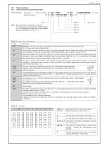
Valve sections Directional spool valve (individual valve) Order examples: PSLF A1 F/320/4 - 3 (valve bank) (individual section) SLF 5 Size Note: Size specification is absolutely necessary! The valve spools are subsequently interchangeable, e.g. if a different flow rating than initially planned becomes necessary (see sect. 6.3.4) Table 16 Table 15 Table 14 Table 13: Spool valve, basic version Coding Standard, with inflow controller, for simultaneous load compensated moving of several consumers (3/3-, 4/3-way spool valve, standard type) Without inflow controller intended for singly / successively...
Open the catalog to page 9All HAWE Hydraulik SE catalogs and technical brochures
 Pressure switch type DG 2025
21 Pages
 VR
VR15 Pages
 BVE
BVE54 Pages
 SLC
SLC17 Pages
 BNG
BNG25 Pages
 BA
BA45 Pages
 VB
VB88 Pages
 VP
VP35 Pages
 VH
VH6 Pages
 SL1
SL115 Pages
 ROLV
ROLV23 Pages
 EM
EM41 Pages
 PS
PS20 Pages
 K60N
K60N19 Pages
 V30D
V30D60 Pages
 V80M
V80M30 Pages
 V30E
V30E51 Pages
 RZ
RZ12 Pages
 Radial piston pump type R, RG
23 Pages
 C40V
C40V47 Pages
 Mini hydraulic power pack type A
23 Pages
 HR 080
17 Pages
 HICON
HICON14 Pages
 INKA
INKA35 Pages
 FXU
FXU35 Pages
 V60N
V60N71 Pages
 Product catalogue
299 Pages


