PS
1 /20Pages

PS
1 /20Pages
Catalog excerpts

Directly mounted CAN controls Product documentation Proportional directional spool valve type PSL and PSV (series connection) Proportional directional spool valve type PSLF and PSVF (manifold mounting)
Open the catalog to page 1
© by HAWE Hydraulik SE. The reproduction and distribution of this document as well as the use and communication of its contents to others without explicit authorisation is prohibited. Offenders will be held liable for the payment of damages. All rights reserved in the event of patent or utility model applications. Brand names, product names and trademarks are not specifically indicated. In particular with regard to registered and protected names and trademarks, usage is subject to legal provisions. HAWE Hydraulik respects these legal provisions in all cases. Printing date / document generated...
Open the catalog to page 2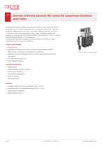
Overview of directly mounted CAN controls for proportional directional spool valves Proportional directional spool valve banks are used to control the direction of movement and the innite adjustment of the movement speed of the hydraulic consumers independent of the load. This allows multiple consumers to be run at the same time and independently of each other at different speeds and pressures, as long as the sum of the partial ow rates required for this is covered by the total delivery ow on the pump side. The electrical connection between the valve sections is via internal cable connections...
Open the catalog to page 4
Available versions, main data 2.1 Order coding, structure Order coding example: PSV 31/D 170-2 CAN-C CANL CAN-E Connector CAN actuation add-on Electrical actuation Table 2 CAN actuation add-on Table 1 Electrical actuation The type codings in bold are described in this document. For all other details, please see D 7700-2, D 7700-3, D 7700-5, D 7700-F and D 7700-7F Table 1 Electrical actuation Marking Combined with manual operation Table 2 CAN actuation add-on At least one connector (marking CAN-C or CAN-T) required on the rst or last valve section. When using a connector on the valve battery,...
Open the catalog to page 5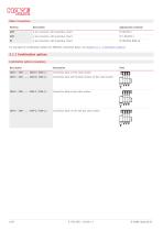
Table 3 Connectors Marking Appropriate connector 4-pin connector, with protective circuit 4-pin connector, with protective circuit 4-pin connector, with protective circuit For examples of combination options for different connection bases, see Chapter 2.1.1, "Combination options" 2.1.1 Combination options Combination options (examples) Description CAN-C - CAN - ... - CAN-E / CAN-L / Connection base on rst valve section CAN-T - CAN - … - CAN-E / CAN-L / Connection base with terminal resistor on rst valve section CAN-E - CAN - … - CAN-C / CAN-L / Connection base on last valve section CAN-C -...
Open the catalog to page 6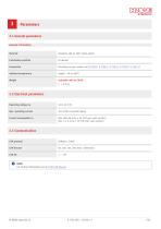
3.1 General parameters General information Material Actuation add-on CAN: nickel-plated Installation position According to type coding, see D 7700-2, D 7700-3, D 7700-5, D 7700-F, D 7700-7F Ambient temperature Actuation add-on EICAN ■ 3.2 Electrical parameters Operating voltage UB Max. 800 mA at UB = 24 V DC (per valve section) Max. 1.5 A at UB = 12 V DC (per valve section) NOTE For further information see B 7700 CAN Manual
Open the catalog to page 7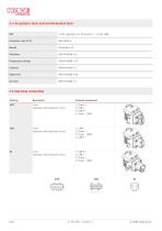
3.4 Acceptance tests and environmental tests EMC Temperature change Damp heat 3.5 Electrical connection Marking Terminal assignment 4-pin Connector with protective circuit 1: Power + 2: CAN-L 3: CAN-H 4: Power - /GND 4-pin Connector with protective circuit 1: CAN-L 2: Power + 3: Power - /GND 4: CAN-H 4-pin Connector with protective circuit 1: CAN-H 2: CAN-L 3: Power + 4: Power - /GND
Open the catalog to page 8
All dimensions in mm, subject to change. 4.1 Actuation add-on Actuation add-on CAN-C, CAN-T and CAN Size 2 (series connection) Size 3 (series connection) Size 5 (series connection)
Open the catalog to page 9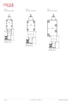
Size 3 (manifold mounting) Size 5 (manifold mounting) Size 7 (manifold mounting)
Open the catalog to page 10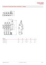
4.2 Structure of valve bank (series connection) – example
Open the catalog to page 11
4.3 Structure of valve bank (manifold mounting) – example
Open the catalog to page 12
Assembly, operation and maintenance recommendations 5.1 Intended use This valve is intended exclusively for hydraulic applications (uid technology), in accordance with Chapter 1. This valve is not intended for end users. The user must observe the safety measures and warnings in the documentation B 7700 CAN Manual. Essential requirements for the product to function correctly and safely: – Observe all information in this documentation and the documentation B 7700 CAN Manual. This applies in particular to all safety measures and warnings. – The product must only be assembled and put into operation...
Open the catalog to page 13
5.2 Operating instructions Note product configuration and pressure / ow rate The statements and technical parameters in this documentation must be strictly observed. The instructions for the complete technical system must also always be followed. Read the documentation carefully before usage. The documentation must be accessible to the operating and maintenance staff at all times. Keep documentation up to date after every addition or update. CAUTION Risk of injury on overloading components due to incorrect pressure settings! Risk of minor injury. ■ ■ Pay attention to the maximum operating pressure...
Open the catalog to page 14
5.3 Maintenance information Conduct a visual inspection at regular intervals, but at least once per year, to check if the hydraulic connections are damaged. If external leakages are found, shut down and repair the system. Clean the device surface of dust deposits and dirt at regular intervals, but at least once per year. 5.4 Safety instructions All installation, set-up, maintenance and repairs must be performed by authorised, qualied and trained staff. The use of this product beyond the specied performance limits, operation with non-specied uids and/or use of non-genuine spare parts will...
Open the catalog to page 15
5.5 Assembly and installation instructions Mounting The valve bank must be mounted free from distortion to the machine chassis or frame. It is recommended to mount using three screws and to use elastic spacers between the block and the frame. Installation To ensure safe operation of the PSl/PSV CAN valve nodes and to avoid shortening the lifetime of the product through improper operating conditions, the following instructions must be observed: ■ ■ ■ ■ The electromagnetic compatibility of the entire system must be ensured by the system manufacturer! Avoid installing the valves near machine parts...
Open the catalog to page 16All HAWE Hydraulik SE catalogs and technical brochures
 Pressure switch type DG 2025
21 Pages
 VR
VR15 Pages
 BVE
BVE54 Pages
 SLC
SLC17 Pages
 BNG
BNG25 Pages
 BA
BA45 Pages
 VB
VB88 Pages
 VP
VP35 Pages
 VH
VH6 Pages
 SL1
SL115 Pages
 ROLV
ROLV23 Pages
 EM
EM41 Pages
 K60N
K60N19 Pages
 V30D
V30D60 Pages
 V80M
V80M30 Pages
 V30E
V30E51 Pages
 RZ
RZ12 Pages
 Radial piston pump type R, RG
23 Pages
 C40V
C40V47 Pages
 Mini hydraulic power pack type A
23 Pages
 HR 080
17 Pages
 HICON
HICON14 Pages
 INKA
INKA35 Pages
 FXU
FXU35 Pages
 V60N
V60N71 Pages
 Product catalogue
299 Pages


