- Catalogs
- HAWE Hydraulik SE
- Pressure-limiting valve type MV.., SV.., DMV..
Pressure-limiting valve type MV.., SV.., DMV..
1 /30Pages

Pressure-limiting valve type MV.., SV.., DMV..
1 /30Pages
Catalog excerpts

Pressure-limiting valve type MV.., SV.., DMV.. Product documentation Operating pressure pmax: Flow rate Qmax:
Open the catalog to page 1
© by HAWE Hydraulik SE. The reproduction and distribution of this document, as well as the use and communication of its contents to others without explicit authorization, is prohibited. Offenders will be held liable for the payment of damages. All rights reserved in the event of patent or utility model applications. Brand names, product names and trademarks are not specifically indicated. In particular with regard to registered and protected names and trademarks, usage is subject to legal provisions. HAWE Hydraulik respects these legal provisions in all cases. HAWE Hydraulik cannot provide individual...
Open the catalog to page 2
Overview Pressure-limiting valve type MV.., SV.., DMV.. Pressure-limiting valves are a type of pressure valve. They safeguard the system against excessive system pressure or limit the operating pressure. Sequence valves generate a constant pressure difference between the inlet and outlet ow. The types MV.., SV.., DMV.. are directly controlled valves that are damped as standard. Features and advantages ■ Operating pressures up to 700 bar ■ Various adjustment options ■ Numerous configurations Intended applications ■ General hydraulic systems ■ Test benches ■ Hydraulic tools Pressure-limiting valve...
Open the catalog to page 4
Available versions 2.4 "Damping" 2.3 "Adjustment" 2.2 "Pressure range and ow rate" 2.1 "Basic type and size" 2.1 Basic type and size Type Ports Available (ISO 228-1) pressure ranges Chapter 2.2 Available adjustments Chapter 2.3 Circuit symbol Angle valve for pipeline installation Pressure-limiting valve and sequence valve MVS Angle valve for pipeline installation Screw-in valve
Open the catalog to page 5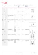
Ports Available (ISO 228-1) pressure ranges Chapter 2.2 Available adjustments Chapter 2.3 Manifold mounting valve Connection plate without coding without coding Circuit symbol Straight-way valve for straight pipeline installation Pressure-limiting valve (as shock valve) for pipeline installation DMV Twin valve for hydraulic motor without coding without coding without coding Twin valve with antiG 3/8 cavitation valve for cylinder G 1/2 2) Single valve with through bores Pressure-limiting valve with free return ow via a bypass check valve MVCS Angle valve for pipeline installation
Open the catalog to page 6
Ports Available (ISO 228-1) pressure ranges Chapter 2.2 Available adjustments Chapter 2.3 Straight-way valve for straight pipeline installation without coding Circuit symbol Conical seat version, service life limited to 50000 cycles; the valve then has to be replaced. Anti-cavitation valves are intended to compensate for volume changes in order to prevent vacuum formation in hydraulic cylinders. 2.2 Pressure range and ow rate Coding Factory-set pressure setting (bar) 1) Flow rate Qmax (lpm) Size 4 if pressure specification missing during ordering for size 8 INFORMATION Lowest achievable pressure...
Open the catalog to page 7
Circuit symbol without coding Fixed, tool adjustable Manually adjustable (Wing bolt + wing nut) Turning knob (self-locking) INFORMATION Factory-set sealing possible (specify in plain text) Only with adjustment “without coding” without coding damped (series)
Open the catalog to page 8
3.1 General data Design Directly controlled pressure valve, in ball seated design MV: Zinc die casting: Standard version for normal operating cases MVS, MVCS: Spheroidal casting: For rough operating conditions. For systems where mechanical shocks or vibrations are unavoidable (vehicle construction). Also in the case of pressure surges in the return line. MVE, MVP, SV, DMV, DMVN, MVT, SVC: Steel Surface protection Steel parts and spheroidal casting, electrogalvanised, spring dome made from zinc die casting, untreated depending on the type, freely hanging in the pipeline or attached over through...
Open the catalog to page 9
3.3 Characteristic lines Viscosity of the hydraulic uid approx. 50 mm2/s Characteristic curve shown based on the example of MV..C (basic trend, certain differences are present depending on the pressure gradient and depending on the housing shape of the various basic types). The characteristic lines change to positive Sp values in the event of increased return pressure. Size 4
Open the catalog to page 11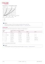
Flow direction R d P with type MVC.. and SVC.. Size 4 Size 5 Size 6 NOTICE Inherent ow resistance in the event of relieved spring (static pressure value 0 bar). Pressures below this boundary are not achievable, see Chapter 3.3, "Characteristic lines" Pressure change Rough reference values (for the closed valve) per 1 revolution on the adjusting screw Pressure (bar) Travel fmax (mm) / Sp (bar) per 1 revolution Size 4 Values in brackets apply for type SV and SVC NOTICE Pressure adjustment only with monitoring of the pressure gauge, see Chapter 6.1, "Setting instructions" HAWE Hydraulik
Open the catalog to page 12
All dimensions in mm, subject to change. Sealing option Adjustment without coding xed Coding R Manually adjustable
Open the catalog to page 13
SW = Width across ats 1 Sealing option Adjustment Coding R Manually adjustable without coding xed Coding V Turning knob
Open the catalog to page 14
Sealing option Adjustment without coding xed Coding R Manually adjustable
Open the catalog to page 15
Sealing option Sealing ring DIN 7603-St-A22x27x1.5 Adjustment without coding xed Coding R Manually adjustable Coding V Turning knob
Open the catalog to page 16
SW = Width across ats 1 2 Sealing option Sealing ring Adjustment Coding R Manually adjustable without coding xed Coding V Turning knob (not with MVE 8) SW = Width across ats
Open the catalog to page 17
Sealing option Centring pin Cylinder screw ISO 4762-M8x35-8.8-A2K Adjustment without coding xed Coding R Manually adjustable Coding V Turning knob Base plate hole pattern
Open the catalog to page 19
SW = Width across ats 1 2 3 Sealing option Centring pin Cylinder screw Adjustment Coding R Manually adjustable without coding xed SW = Width across ats HAWE Hydraulik
Open the catalog to page 20
Base plate hole pattern Sealing option Centring pin Cylinder screw Base plate hole pattern
Open the catalog to page 21
SW = Width across ats Sealing option Sealing option
Open the catalog to page 22
Sealing option Sealing option
Open the catalog to page 23
Sealing option SW = Width across ats 1 Sealing option
Open the catalog to page 24All HAWE Hydraulik SE catalogs and technical brochures
 Pressure switch type DG 2025
21 Pages
 VR
VR15 Pages
 BVE
BVE54 Pages
 SLC
SLC17 Pages
 BNG
BNG25 Pages
 BA
BA45 Pages
 VB
VB88 Pages
 VP
VP35 Pages
 VH
VH6 Pages
 SL1
SL115 Pages
 ROLV
ROLV23 Pages
 EM
EM41 Pages
 PS
PS20 Pages
 K60N
K60N19 Pages
 V30D
V30D60 Pages
 V80M
V80M30 Pages
 V30E
V30E51 Pages
 RZ
RZ12 Pages
 Radial piston pump type R, RG
23 Pages
 C40V
C40V47 Pages
 Mini hydraulic power pack type A
23 Pages
 HR 080
17 Pages
 HICON
HICON14 Pages
 INKA
INKA35 Pages
 FXU
FXU35 Pages
 V60N
V60N71 Pages
 Product catalogue
299 Pages


