NSWP 2
1 /8Pages

NSWP 2
1 /8Pages
Catalog excerpts

Directional spool valve type NSWP 2 Manifold mounting valve with connection hole pattern conforming DIN 24 340 - A 6 (NG 6) Operation pressure pmax = 315 bar Flow Qmax = 25 lpm See also: o Directional spool valve o Directional valve bank o Directional valve bank o Clamping modules o Directional seated valves o Directional seated valves o Valve banks o Intermediate plates type SW 2 type SWR 2 type SWS 2 type NSMD 2 type NG etc. type NBVP 16 type BA 2 type NZP General information Type NSWP 2 was developed as addition to the other already available directional spool valves type SW 2, SWP 2, SWR 2 acc. to D 7451, and SWS 2 acc. to D 7951. Special features: o Industrial standard connection hole pattern o Directly mounted pressure switch monitoring the consumer port o Various actuation solenoid versions o Rapid traverse-creeping circuitry o Differing flow ratings of the spools for the for proportional or throttle spool versions o Optional elements in the pump, consumer, and return port o Individual connection block for direct pipe connection Pump port P Orifice B.. Check valve R.. Return pressure stop S. HAWE HYDRAULIK SE STREITFELDSTR. 25 • 81673 MÜNCHEN © 1999 by HAWE Hydraulik ABV.. ABR.. BBV.. BBR.. Restrictor check valves (Observe installation position!) Directional spool valve type NSWP 2 December 2007-0
Open the catalog to page 1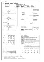
Available versions, main data NSWP 2 W/M/20 - WG 230 1) NSWP 2 D 06/MP /R/ABR 1,0/20 /S - G 24 NSWP 2 G /MM66/R /50 /B 1,0 - G 24 - 3/8 Order example 1 Order example 2 Order example 3 Individual connection block for direct pipe connection Additional elements at port P (see table 4) Actuation solenoid (see table 8) Additional elements at port T (see table 7) Solenoid version (see table 3) Pressure switch or pressure gauge (see table 6) Additional elements for ports A and/or B (see table 5) Table 1: Basic type Coding, description NSWP 2 With industrial standard hole pattern DIN 24 340-A 6 Table...
Open the catalog to page 2
D 7451 N page 3 Table 5: Additional elements for ports A and/or B Table 4: Additional elements at port P Coding 1) Additional element (also in combination) without Orifice Coding 1) 2) at port A at port B Additional element Orifice in A and/or B Restrictor check valve at A and/or B throttling in direction to the consumer Restrictor check valve at A and/or B unthrottled flow to the consumer Check valve Table 6: Pressure switch or pressure gauge at port A or B Pressure switch acc. to D 5440 (adjustable range) without DG (prepared for retrofitting) Pressure gauge acc. to D 7077 with scale up to...
Open the catalog to page 3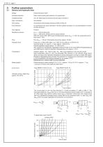
Further parameters General and hydraulic data Design Directional spool valve Surface protection Spool valve housing and solenoid, zinc galvanized Installed position Any, for fastening see dimensional drawings in section 4 Hydr. connection Port coding According to dimensional drawing or DIN 24 340-A 6 Flow direction In accordance with arrow direction in the flow pattern symbols; It is not permissible to reverse the flow direction! Over lapping Operation pressure pmax = 315 bar (all ports) pmax = 200 bar for version with ex-proof solenoid and with version /MP, /MPF (pure throttling spool valve),...
Open the catalog to page 4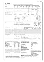
Wet armature solenoid, manufactured and tested conforming VDE 0580 Reference value for nom. power PN , 24.4 W * approx. 6% dep. on nom. voltage UN and make 12 V DC 24 V DC 24 V DC 48 V DC 80 V DC 98 V DC 205 V DC 110 V AC Nominal voltage UN 50/60Hz 50/60Hz Port and circuitry (valid for solenoid a and b) Gray plug Black plug Coding G (...V DC) is only available with gray or black plugs. Coding WG (..V AC) is only available with black plugs, featuring an internal bridge rectifier circuit Relative duty cycle Duty cycle (%) Switching times (ref. value) Switching operations Protection class IP 65...
Open the catalog to page 5
Unit dimensions All dimensions in mm, subject to change without notice ! 4/3- and 4/2-way directional spool valves coding G, D, E, O, K (Illustration with solenoid /M, for other solenoids see below) 4/2-way directional spool valve Coding W Additional solenoids acc. to table 3, sect. 2 Hole pattern of the manifold (top view) Manual emergency actuation /MD For missing specifications, see above! a = 29 (G 12 to G 205); 34 (WG 230) This dimension depends on the manufacturer and may be up to 40 mm acc. to EN 175 301-803 A ! Solenoid c for 2. speed rate
Open the catalog to page 6
D 7451 N page 7 Version with individual connection block Ports conf. ISO 228/1 (BSPP): A, B, P, T = G 3/8 (M = G 1/4) M, can be used only together with clamping module type NSMD acc. to D 7787 Notes regarding the uneven solenoid actuation The notes below have to be observed, when differing solenoid versions are to be combined for a and b: Order examples: /MM 6 - MK /M - MD Magnet a Attention: The stroke limitation (/MK or /MD) at these examples is only active for solenoid a (/MM 6 or /M). Combination possibilities Solenoid b Solenoid a /M, /MD, /MK 2) /MP, /MPF 2) /MM.. /M, /MD, /MK o --- o ---...
Open the catalog to page 7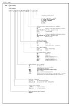
Type coding Order example: NSWP 2 D 06/M/B0,8R/ABR1,0/20/ S - G 24 - 3/8 Individual connection block Nominal voltage (acc. to table 8) G 12, G 24, WG 110, WG 230 X 12, X 24, X 98, X 205 L 12, L 24 G 24 EX Additional function, pressure switch (acc. to table 6) Port B: Without (prepared for retrofitting of a DG 3..) 02 03, 04, 05, 06, 07 With DG 3.. (acc. to D 5440) B 9/... Pressure gauge Port A: 20 Without (prepared for retrofitting of a DG 3..) 30, 40, 50, 60, 70 With DG 3.. (acc. to D 5440) A 9/... Pressure gauge Additional elements Port P (acc. to table 4) B ... Orifice Check valve R B.. R...
Open the catalog to page 8All HAWE Hydraulik SE catalogs and technical brochures
 Pressure switch type DG 2025
21 Pages
 VR
VR15 Pages
 BVE
BVE54 Pages
 SLC
SLC17 Pages
 BNG
BNG25 Pages
 BA
BA45 Pages
 VB
VB88 Pages
 VP
VP35 Pages
 VH
VH6 Pages
 SL1
SL115 Pages
 ROLV
ROLV23 Pages
 EM
EM41 Pages
 PS
PS20 Pages
 K60N
K60N19 Pages
 V30D
V30D60 Pages
 V80M
V80M30 Pages
 V30E
V30E51 Pages
 RZ
RZ12 Pages
 Radial piston pump type R, RG
23 Pages
 C40V
C40V47 Pages
 Mini hydraulic power pack type A
23 Pages
 HR 080
17 Pages
 HICON
HICON14 Pages
 INKA
INKA35 Pages
 FXU
FXU35 Pages
 V60N
V60N71 Pages
 Product catalogue
299 Pages


