
- Catalogs
- HAWE Hydraulik SE
- NBVP 16


NBVP 16

NBVP 16
Directional seated valves, such as the NBVP type, are designed to control hydraulic flow with zero leakage. These valves are manifold mounted with standard connection patterns and come in configurations like 2/2, 3/2, 4/2, 4/3, and 4/4-way. Key features include position monitoring, explosion-proof versions, and optional solenoids, suitable for applications in machine tools, clamping tools, and wind turbines.
Available Versions
The document describes various NBVP valve versions, including basic types, circuit symbols, and additional elements at different ports. It provides ordering examples and stresses the importance of adhering to maximum operating pressures.
Parameters
This section details general data, pressure and flow rates, weight, characteristic lines, and electrical data. It highlights the necessity of correct electrical actuation and provides specifications for contact switches.
Dimensions
Dimensions for the valve, actuating elements, and pressure switches are provided, along with diagrams for different actuation types. Correct installation is emphasized.
Installation, Operation, and Maintenance
Guidelines for intended use, assembly, operation, and maintenance are outlined, stressing the importance of following these instructions for optimal performance and safety.
Other Information
Details on accessories, spare parts, and individual components are provided to ensure users have access to necessary resources for maintenance and repair.
Specifications
The document outlines various actuation systems with different power ratings at specified voltages (48 V DC, 98 V DC, 205 V DC). It includes dimension diagrams labeled A to G, detailing power consumption for different models. Switching times are approximately 50 to 60 ms, with some models taking longer. The contact temperature is 120°C at 20°C ambient temperature, and the insulation material class is F.
Electrical Data
For explosion-proof solenoids, the nominal voltage is 24 V DC with a nominal power of 23 W. Certifications like ATEX are mentioned, along with surface protection details and cable kit specifications. Mixing excitation and actuating systems is discouraged.
Mechanical and Inductive Contact Switches
Mechanical contact switches have a service life of 5 million cycles, while inductive contact switches have a service life of 4830 years with a maximum switching frequency of 1 Hz. Protection classes IP 65 and IP 54 are specified for plug connections.
Alternative Actuations
Includes hydraulic, pneumatic, manual, and mechanical options with specific coding and permissible pressure details. Specifications for control volume, housing material, and actuation force are provided.
Dimensions and Installation
Dimensions for components like the base plate, valve parts, and actuating elements are provided. Detailed instructions for manual actuation and the use of auxiliary tools are included, emphasizing safety measures and the need for specialist personnel during assembly.
Safety and Maintenance
The document stresses the importance of adhering to safety measures and warnings. It outlines the intended use for hydraulic applications and provides guidelines for assembly, operation, and maintenance, warning against incorrect disassembly.
Introduction
This document outlines the technical specifications and operational guidelines for HAWE Hydraulik SE products, emphasizing adherence to parameters and instructions for safe and efficient operation.
General Instructions
Users must read the documentation thoroughly before use and ensure it is accessible to all operating and maintenance staff. Documentation should be updated with every addition or update.
Safety Precautions
Incorrect pressure settings can overload components, posing a risk of minor injury. Users must monitor the pressure gauge when setting or changing pressure and adhere to the maximum operating pressure of pumps, valves, and fittings.
Hydraulic Fluid Purity and Filtering
Fine contamination can impair product function and cause damage. New hydraulic fluid should be filtered before use, and mixing different hydraulic fluids is discouraged.
Maintenance Information
Regular visual inspections are necessary to check for damage to hydraulic connections. Any external leakages should prompt system shutdown and repair. Device surfaces should be cleaned regularly.
Accessories and Spare Parts
Spare parts can be purchased through HAWE Hydraulik's interactive contact map. Specific coding and part numbers are provided for various components.
Additional Information
References to additional versions of valves and components are provided, including directional seated valves and valve banks.
Contact Information
HAWE Hydraulik SE is located in Aschheim/Munich, Germany. Contact details and further information are available on their website.
Catalog excerpts

Directional seated valve type NBVP 16 Product documentation Operating pressure pmax: Flow rate Qmax:
Open the catalog to page 1
© by HAWE Hydraulik SE. The reproduction and distribution of this document, as well as the use and communication of its contents to others without explicit authorization, is prohibited. Offenders will be held liable for the payment of damages. All rights reserved in the event of patent or utility model applications. Brand names, product names and trademarks are not specifically indicated. In particular with regard to registered and protected names and trademarks, usage is subject to legal provisions. HAWE Hydraulik respects these legal provisions in all cases. HAWE Hydraulik cannot provide individual...
Open the catalog to page 2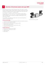
Overview of directional seated valve type NBVP Directional seated valves are a type of directional valve. Their function is to direct the ow of hydraulic medium in certain directions, therefore connecting the relevant connections, or shutting off the ow with zero leakage. By this means they control the movement of the actuators in a hydraulic system. The type NBVP is a manifold mounting valve with standard connection pattern nominal size NG 6. 2/2-, 3/2-, 3/3-, 4/2-, 4/3- and 4/4-way directional seated valves with different types of actuation are available. All listed types are coneseated valves...
Open the catalog to page 5
Available versions Circuit symbol examples NBVP 16 S/B 0.8 /2 - WG 110 Ordering examples NBVP 16 NBVP 16 NBVP 16 -3/8 -1/4 4.6 "Single connection block" 2.7 "Actuations" 2.6 "Additional elements at port T" 2.5 "Pressure switches and/or pressure gauges at the ports A and/or B" 2.4 "Additional elements at port A and/or B" 2.3 "Additional elements at port P or P1 and P2" 2.2 "Circuit symbol" 2.1 "Basic type and size" 2.1 Basic type and size Type Flow rate Qmax (lpm) With standard connection pattern NG 6 in accordance with DIN 24 340-A6 or CETOP 03 in accordance with ISO 4401-03 NOTICE Observe the...
Open the catalog to page 6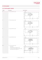
2.2 Circuit symbol 2.2.1 Circuit symbols, standard Coding Circuit symbol 3/2-way directional valve – With detent – Only with electrical actuation G, WG – In the case of several adjacent valves, install return pressure stop coding S in T.
Open the catalog to page 7
Circuit symbol HAWE Hydra
Open the catalog to page 8
Circuit symbol 4/2-way directional valve – pmax = 250 bar 4/2-way directional valve – With detent 3/3-way directional valve – a + b = 4. Switching position due to simultaneous energization of both solenoids 4/3-way directional valve – a + b = 4. Switching position due to simultaneous energization of both solenoids 4/3-way directional valve – a + b = 4. Switching position due to simultaneous energization of both solenoids
Open the catalog to page 9
Circuit symbol 4/3-way directional valve – a + b = 4. Switching position due to simultaneous energization of both solenoids 4/3-way directional valve – a + b = 4. Switching position due to simultaneous energization of both solenoids 4/3-way directional valve – a + b = 4. Switching position due to simultaneous energization of both solenoids
Open the catalog to page 10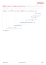
2.2.2 Circuit symbols, 4/4-way directional seated valves Ordering example "Additional elements at port T" "Pressure switches and/or pressure gauges at port B" "Additional elements at port B" "Additional elements at P2" "Pressure switches and/or pressure gauges at port A" "Additional elements at port A" "Additional elements at P1" "Additional elements at port P" "Circuit symbols, 4/4-way directional seated valves" "Basic type and size"
Open the catalog to page 11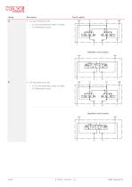
Circuit symbol 4/4-way directional valve – 2x 3/2-way directional valves in a block – For differential circuits Simplied circuit symbol 4/4-way directional valve – 2x 3/2-way directional valves in a block – For differential circuits Simplied circuit symbol
Open the catalog to page 12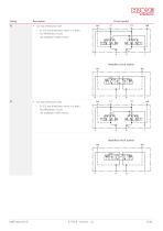
Circuit symbol 4/4-way directional valve – 2x 3/2-way directional valves in a block – For differential circuits – not available in ATEX version Simplied circuit symbol 4/4-way directional valve – 2x 3/2-way directional valves in a block – For differential circuits – not available in ATEX version Simplied circuit symbol
Open the catalog to page 13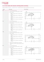
2.2.3 Circuit symbols with inductive switching position monitoring Ordering example see Chapter 2, "Available versions". Inductive position monitoring directly at the valve plug. Coding Circuit symbol 2/2-way directional valve only with electrical actuation XM24, X24/30W Circuit symbol – RUO: with DIN connector (normally closed contact) – RUS: with DIN connector (normally open contact) – RUMO: with M12 connector (normally closed contact) – RUMS: with M12 connector (normally open contact) 2/2-way directional valve only with electrical actuation XM24, X24/30W Circuit symbol – SUO: with DIN connector...
Open the catalog to page 14
Circuit symbol 3/2-way directional valve only with electrical actuation XM24, X24/30W Circuit symbol – YUO: with DIN connector (normally closed contact) – YUS: with DIN connector (normally open contact) – YUMO: with M12 connector (normally closed contact) – YUMS: with M12 connector (normally open contact) INFORMATION Inductive contact switch see Chapter 3.5.2, "Electrical data for contact switch"
Open the catalog to page 15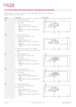
2.2.4 Circuit symbols with contact switch for switching position monitoring Ordering example see Chapter 2, "Available versions". Direct position monitoring of the valve plug. Overlap see Chapter 3.1, "General data" Coding Circuit symbol 2/2-way directional valve only with electrical actuation G, WG Circuit symbol – RK..: with DIN connector – RKM: with M12 connector (normally open contact) – RKMO: with M12 connector (normally closed contact) 3/2-way directional valve only with electrical actuation G, WG Circuit symbol – STK: with DIN connector – STKM: with M12 connector (normally open contact)...
Open the catalog to page 16All HAWE Hydraulik SE catalogs and technical brochures
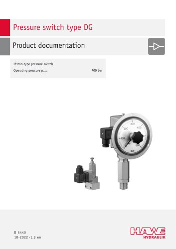 Pressure switch type DG 2025
21 Pages
 VR
VR15 Pages
 BVE
BVE54 Pages
 SLC
SLC17 Pages
 BNG
BNG25 Pages
 BA
BA45 Pages
 VB
VB88 Pages
 VP
VP35 Pages
 VH
VH6 Pages
 SL1
SL115 Pages
 ROLV
ROLV23 Pages
 EM
EM41 Pages
 PS
PS20 Pages
 K60N
K60N19 Pages
 V30D
V30D60 Pages
 V80M
V80M30 Pages
 V30E
V30E51 Pages
 RZ
RZ12 Pages
 Radial piston pump type R, RG
23 Pages
 C40V
C40V47 Pages
 Mini hydraulic power pack type A
23 Pages
 HR 080
17 Pages
 HICON
HICON14 Pages
 INKA
INKA35 Pages
 FXU
FXU35 Pages
 V60N
V60N71 Pages
 Product catalogue
299 Pages


