


HSF

HSF
Catalog excerpts
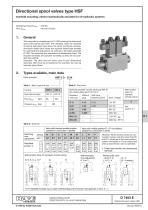
Directional spool valves type HSF manifold mounting, eIectro-hydraulicaIIy actuated for oil-hydraulic systems Operating pressure pmax = 400 bar = 80 and 160 lpm Flow Qmax General This pamphlet is a supplement to D 7493 covering the directional spool valve banks type HSR. The individual valves for manifold mounting described here share the same functional principle, directional seated pilot valves and optional thread-type throttles for switching time adjustment, as outlined in the basic pamphlet D 7493. The switching time adjustment is detailed also there. The required manifolds are customer furnished, as they are not available from HAWE. Important: The valve has two outlet ports R (see dimensional sketches). Both must be connected at the manifold, but may be internally joined there. Types available, main data Order example: Table 1: Basic type and size Table 3: Pilot valve Nominal size appr. Flow Qmax Solenoid actuated via pilot valve type WN 1H (for missing data, see D 7470 A/1) Standard, with plug With plug featuring LED’s Without plug Without pilot valve, for hydraulic remote control Table 2: Symbols Valve with blocked middle position, suitable for connection in parallel Switching time adjustment without with Valve with middle position P→ R (circulation), suitable for connection in series Attention: When several valves are connected in series, note that when the H(1) and F(1) valves are in their zero position, outlets connected to R are pressurized when a downstream valve is operated. 1) Without pilot valve, for hydraulic remote control G, D, E, C, L, H, F With switching time adjustment G 1 to F 1 Thread type throttle, see dimensional drawings. Without pilot valve ...G (D, E, C, ...W - X L, H, F) - X (..B - X analog.) For detailed symbols e.g. to ease understanding of the function, see appendix in sect. 5 ++. HAWE HYDRAULIK SE STREITFELDSTR. 25 • 81673 MÜNCHEN © 1988 by HAWE Hydraulik D 7493 E Directional spool valves HSF January 20
Open the catalog to page 1
General parameter Type and version Directional spool valve, full steel design. Housing zinc galvanized, giving a good resistance to corrosion. Valve spools hardened, ground and polished/deburred. Together with the diamond-honed and polished and deburred housing bore, this gives an exactly circular and even sealing gap with a minimum leakage rate. BuiIt-on directional ball seated valves type WN 1H acc. to D 7470 A/1 as pilot valves Installation position Line connection Via manifold, customer-furnished, as not available from HAWE Port coding Pump inlet Return. Important: 2 ports! (exception coding...
Open the catalog to page 2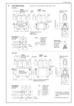
Unit dimensions All dimension in mm and subject to change without notice! Cable gland Manual emergency actuation Max. torque 39 Nm Tapped plug (without switching time adjustment) Screw for switching time adjustment Allan head a/f 3 Hole pattern of the manifold (top view) Sealing of the flange area via O-ring NBR 90 Sh Manual emergency actuation Actuation aid (do not use any sharpedged tools) Cable gland Manual emergency actuation Tapped plug (without switching time adjustment) Screw for switching time adjustment Hexagon head screw a/f 10 ( X,Z) Hole pattern of the manifold (top view) Sealing...
Open the catalog to page 3
Detailed flow symbols Examples not listed should be drawn accordingly. Control port X serves as drain/leakage port to the tank with spools W1 and B1. Standard version with pilot valves To the tank or to port P of a subsequent spool valve coding L, F, or H Version ...-X, without pilot valve In the case of 4/3-way versions with switching time adjustment (e.g. G1, D1 etc.), only the control port Z can be influenced via the throttle screw. In the case of control port X, it is necessary to install a throttle (e.g. FG or FG-S 6 acc. to D 7275) externally into the connected control line. The symbol...
Open the catalog to page 4All HAWE Hydraulik SE catalogs and technical brochures
 Pressure switch type DG 2025
21 Pages
 VR
VR15 Pages
 BVE
BVE54 Pages
 SLC
SLC17 Pages
 BNG
BNG25 Pages
 BA
BA45 Pages
 VB
VB88 Pages
 VP
VP35 Pages
 VH
VH6 Pages
 SL1
SL115 Pages
 ROLV
ROLV23 Pages
 EM
EM41 Pages
 PS
PS20 Pages
 K60N
K60N19 Pages
 V30D
V30D60 Pages
 V80M
V80M30 Pages
 V30E
V30E51 Pages
 RZ
RZ12 Pages
 Radial piston pump type R, RG
23 Pages
 C40V
C40V47 Pages
 Mini hydraulic power pack type A
23 Pages
 HR 080
17 Pages
 HICON
HICON14 Pages
 INKA
INKA35 Pages
 FXU
FXU35 Pages
 V60N
V60N71 Pages
 Product catalogue
299 Pages


