EM
1 /41Pages

EM
1 /41Pages
Catalog excerpts
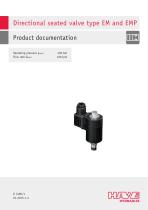
Directional seated valve type EM and EMP Product documentation Operating pressure pmax: Flow rate Qmax:
Open the catalog to page 1
© by HAWE Hydraulik SE. The reproduction and distribution of this document as well as the use and communication of its contents to others without explicit authorisation is prohibited. Offenders will be held liable for the payment of damages. All rights reserved in the event of patent or utility model applications. Brand names, product names and trademarks are not specifically indicated. In particular with regard to registered and protected names and trademarks, usage is subject to legal provisions. HAWE Hydraulik respects these legal provisions in all cases. Printing date / document generated...
Open the catalog to page 2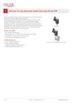
Overview 2/2-way directional seated valves type EM and EMP Directional seated valves are a type of directional valve. As cone valves they are tightly sealed without leakage in the closed state. The directional seated valves type EM and EMP are screw-in valves. 2/2-way directional seated valves with direct or pilot-controlled electromagnetic actuation are available. The directional seated valve type EM is available as a directional. Type EMP is a proportionally switching directional seated valve. Appropriate connection blocks make possible direct pipe connection or manifold mounting. You can obtain...
Open the catalog to page 4
Available versions, main data 2.1 directional seated valves, directional valve Symbol: Function lock Actuation solenoid Single connection block Basic type und size Table 5 Seal spec. Table 1a Mechanical function block of the valve Table 4 Actuation solenoid Single connection block Chapter 2.4, "Single connection blocks" Table 1 Basic type und size Table 1 Basic type and size Basic type and size Volumetric ow direction Symbol AdB B d A = Free volumetric ow, solenoid must be deenergized
Open the catalog to page 5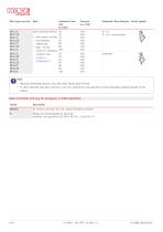
Basic type and size Volumetric ow direction Circuit symbol pilot-controlled shifting 20 20 ■ with manual override, 40 not displayed 40 80 additionally 80 ■ Type ..ST with button for emergency 160 actuation (see Chapter 4, "Dimensions") Maximal permissible pressure only with basic blocks made of steel. If other materials have been used (e.g. cast iron, aluminium), pay attention to the potentially reduced strength of the thread. Table 1a Function lock (e.g. for emergency- or initial operation) Coding No function lock (std.) but incl. manual emergency actuation Winged nut (xed laterally via lead...
Open the catalog to page 6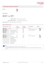
2.2 Directional seated valve, soft-shift Symbol: - WG 230 - 3/4 - G 24 Actuation solenoid Single connection blocks Basic type and size Table 4 Actuation solenoid Table 6a Single connection blocks Table 2 Basic type and size, soft-shift Table 2 Basic type and size Basic type and size 40 40 Typ .VG 10(20) with 40 customized throttling 40 80 characteristic (see 160 curves, Chapter 3, "Parameters") 40 40 With manual 40 emergency actuation 80 (not detailed) Typ .SG 10(20) with customized throttling characteristic, (see curves, Chapter 3, "Parameters") Flow direction AdB B d A = Free ow, solenoid...
Open the catalog to page 7
2.3 Proportional directional seated valve, proportional throttle Symbol: Actuation solenoid Single connection blocks Basic type and size Table 1a Function lock Table 4 Actuation solenoid Table 6a Single connection blocks Table 3 Basic type and size, proportional Table 3 Basic type and size Basic type and size 40 40 Typ ..V 10(20,80) 40 with customized 40 throttling character- 40 80 istic (see curves, 70 Chapter 3, 80 "Parameters") 100 Type ..VH with stroke 160 limitation 40 40 With manual 40 emergency actuation 80 (not detailed) (see curves, Chapter 3, "Parameters") Volumetric ow direction Symbol...
Open the catalog to page 8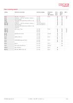
Table 4 Actuating solenoid Coding Electrical connection Nominal voltage DIN EN 175 301-803 A (Coding G... with line connector, coding L... with LED plug) Coding WG with alternating rectifier in line connector (Coding G... with line connector, coding L... with LED plug) Coding WG with alternating rectifier in line connector Free cable ends 600 mm
Open the catalog to page 9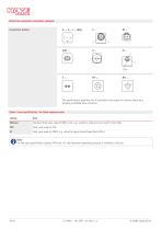
Electrical connection Actuation solenoid G .., X.., L .. (WG) Connection pattern The specifications regarding the IP protection class apply for versions featuring a properly assembled male connector. Table 5 Seal specification, for uid exposed seals Coding Standard, uid seals made of NBR or AU, e.g. suited for mineral oil and synth. Ester HEES Fluid seals made of FKM Fluid seals made of EPDM, e.g. suited for glycol based brake uid (DOT4) Note For the seal specification coding -PYD and -AT, the maximum operating pressure is limited to 250 bar.
Open the catalog to page 10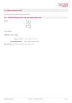
2.4 Single connection blocks Suited for direct pipe connection of manifold mounting 2.4.1 Single connection blocks with and without drain valve Symbol: Single connection blocks Basic type and size Table 4 Actuation solenoid Table 6 Single connection blocks Basic type and size acc. to table 1, 2, 3
Open the catalog to page 11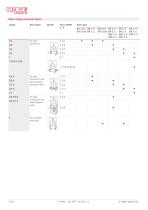
Table 6 Single connection blocks Coding For pipe connection with (accumulator) discharge valve For pipe connection with manual bypass valve
Open the catalog to page 12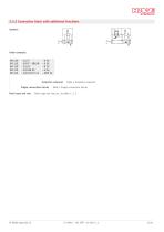
2.4.2 Connection block with additional functions Symbol: Single connection blocks Basic type and size Table 4 Actuation solenoid Table 7 Single connection blocks Basic type and size acc. to table 1, 2, 3
Open the catalog to page 13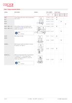
Table 7 Single connection blocks Coding Swivel tting with drain valve (accumulator drain valve) Swivel tting, drop-rate braking valve according to D 6920 and drain valve; for details, see Table 7a With bypass throttle With pressure switch according to D 5440; for details, see Table 7b With load-independent ow rate limitation in direction B d F with type SJ ow control valves according to D 7395; for details, see Table 7c
Open the catalog to page 14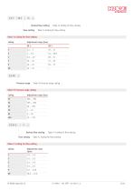
Desired ow setting Flow setting Table 7a Coding for ow setting Table 7a Coding for ow setting Table 7a Coding for ow setting Coding Pressure range Table 7b Pressure range coding Table 7b Pressure range coding Coding Flow setting Table 7c Coding for ow setting Table 7c Coding for ow setting Table 7c Coding for ow setting Coding
Open the catalog to page 15
2.5 Valve combinations 2.5.1 Valve banks type BEM Symbol: Ports Valve section Basic type and size Table 11 Actuation solenoid Table 9 Valve section Table 8 Basic type and size Table 8 Basic type and size Basic type BEM 11 Flow rate Qmax (lpm)
Open the catalog to page 16All HAWE Hydraulik SE catalogs and technical brochures
 Pressure switch type DG 2025
21 Pages
 VR
VR15 Pages
 BVE
BVE54 Pages
 SLC
SLC17 Pages
 BNG
BNG25 Pages
 BA
BA45 Pages
 VB
VB88 Pages
 VP
VP35 Pages
 VH
VH6 Pages
 SL1
SL115 Pages
 ROLV
ROLV23 Pages
 PS
PS20 Pages
 K60N
K60N19 Pages
 V30D
V30D60 Pages
 V80M
V80M30 Pages
 V30E
V30E51 Pages
 RZ
RZ12 Pages
 Radial piston pump type R, RG
23 Pages
 C40V
C40V47 Pages
 Mini hydraulic power pack type A
23 Pages
 HR 080
17 Pages
 HICON
HICON14 Pages
 INKA
INKA35 Pages
 FXU
FXU35 Pages
 V60N
V60N71 Pages
 Product catalogue
299 Pages


