EDL
1 /34Pages

EDL
1 /34Pages
Catalog excerpts

Proportional directional spool valve type EDL Product documentation Series connection Operating pressure pmax: Flow rate Vmax:
Open the catalog to page 1
© by HAWE Hydraulik SE. The reproduction and distribution of this document as well as the use and communication of its contents to others without explicit authorisation is prohibited. Offenders will be held liable for the payment of damages. All rights reserved in the event of patent or utility model applications. Brand names, product names and trademarks are not specifically indicated. In particular with regard to registered and protected names and trademarks, usage is subject to legal provisions. HAWE Hydraulik respects these legal provisions in all cases. Printing date / document generated...
Open the catalog to page 2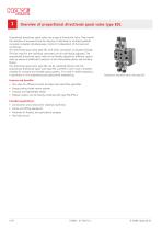
Overview of proportional directional spool valve type EDL Proportional directional spool valves are a type of directional valve. They control the direction of movement and the velocity of individual or multiple hydraulic consumers actuated simultaneously. Control is independent of the load and continuous. The directional spool valve type EDL with series connection is actuated directly. The ow rates for the individual consumers can be individually adjusted. The proportional directional spool valve can be exibly adapted to different control tasks by means of additional functions in the intermediate...
Open the catalog to page 4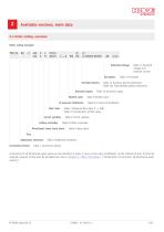
Available versions, main data 2.1 Order coding, overview Order coding example: PSV 3X End plates Ancillary blocks Actuation types Shuttle valve LS pressure limitation Flow rates Table 12 Ancillary blocks (selection) Table 12a Intermediate plates (selection) Table 10 Actuation types Table 9 Shuttle valve Table 8 LS pressure limitation Table 7 Maximum ow rates P d A(B) Table 7a Combination of ow rates Circuit symbols Inow controller Table 11 Solenoid voltage and solenoid version Table 6 Circuit symbols Table 5 Inow controller Directional valve, basic block Table 4 Basic block Size Additional...
Open the catalog to page 5
2.2 Connection blocks and end plates There are the following basic variants of connection blocks: ■ ■ Connection blocks with integrated 3-way controller when using a constant pump system (open centre) – type PSL Connection blocks for use with variable pump systems (closed centre), constant pressure systems or for parallel oil supply of multiple physically separate directional spool valve banks in the second and all further valve blocks – type PSV Adapter plates for combining proportional directional spool valves type PSL and PSV, size 3 and 5 Order coding of a single connection block (example):...
Open the catalog to page 6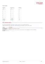
Table 2 Additional elements (For notes and explanation, see Chapter 6, "Other information" ("On connection blocks")) Additional elements only suitable where variable pumps are used (limitation of the control oil ow). Coding Standard, without additional element Orice # 0.4 mm, 0.5 mm, 0.6 mm, 0.7 mm or 0.8 mm in the LS gallery (for control oil limitation)
Open the catalog to page 7
2.2.2 End plates Order coding example: PSV 3 X - 2 Table 3 End plates Coding Circuit symbol End plate without additional function, not in combination with valve sections SL2, SL3 or SL5 • Can only be used with max. three sections • Only in conjunction with shuttle valve, coding W 3, Table 9 in last valve section Operating pressure max = 250 bar! With control oil return line T external to tank Like E 1, with additional port Y for connection to the LS outlet of another, separately arranged PSV spool block Like E 1, however control oil return line is internal, maximum return pressure of 10 bar!...
Open the catalog to page 8
2.3 Valve section 2.3.1 Directional valve Order coding example: PSV 31/D250 - 2 - Ancillary blocks Actuation types LS pressure limitation Flow rates Table 10 Actuation types Table 8 LS pressure limitation Table 7 Maximum ow rates P d A(B) Table 7a Combination of ow rates Circuit symbols Inow controller Table 12 Ancillary blocks (selection) Table 12a Intermediate plates (selection) Table 6 Circuit symbols Table 5 Inow controller Directional valve, basic block Order coding of the single valve section (examples): Table 4 Basic block Valve section Valve spool (single) The size specification is...
Open the catalog to page 9
Table 4 Basic block Coding Complete valve section with an ancillary block in accordance with Table 12 D 7700-2 Circuit symbol With respect to main ow and actuation, the circuit symbols are neutral and must be supplemented by the corresponding circuit symbols given according to Table 6 to 10, Chapter 6, see also examples in Table 10 4/3-way directional spool valve with inow controller Example: - DA 7 H40/40/E/2 (-DT 12) 4/3-way directional spool valve with inow controller and LS pressure limitation Example: - DA 2 L25/16 C 200 /E/2 (- X 24) 1 Ancillary block and intermediate block acc. to D...
Open the catalog to page 10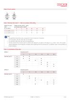
Table 6 Circuit symbols L Table 7 Maximum ow rates P d A(B) in accordance with coding Coding for spool valve acc. to Table 6 Coding for ow rate QA, B (lpm) at consumer ports A and B 3 The specied nominal ow rates correspond to the set values for E actuation. For EI actuation, the max. ow rates can be higher. The maximum reux ow rate must not exceed 80 lpm. The ow rates for the consumer ports A and B can be selected in accordance with Table 7a, e.g. 40/25, 16/16. This enables optimal adaptation to the respective consumer while exploiting the full functional lift. In addition, there is...
Open the catalog to page 11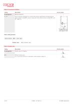
Table 8 LS pressure limitation Coding Circuit symbol Without protection Joint LS pressure limitation for A and B with pressure specification and load pressure, signal output G 1/8 (BSPP), only in conjunction with solenoid version coding AMP.. and DT.. (Table 11) Order coding example: DA 2 L 25/16 Shuttle valve Table 9 Shuttle valve Table 9 Shuttle valve Coding Shuttle valve in LS gallery Without shuttle valve, e.g. in last valve section for combination with end plate coding E 0 Circuit symbol
Open the catalog to page 12
Table 10 Actuation types Coding Circuit symbol Electrical actuation with stroke limitation Electrical actuation with manual override Electrical actuation with manual override, A-side only Electrical actuation with manual override, B-side only For reference values for start of ow at A or B (= min.) up to max. usable volume ow in accordance with Table 7, see Chapter 3.2, "Characteristics" The solenoid voltage and solenoid version are dened at the end of the type designation and applies to all solenoids in the valve bank, see Table 11 Table 11 Solenoid voltage and solenoid version Coding Electrical...
Open the catalog to page 13All HAWE Hydraulik SE catalogs and technical brochures
 Pressure switch type DG 2025
21 Pages
 VR
VR15 Pages
 BVE
BVE54 Pages
 SLC
SLC17 Pages
 BNG
BNG25 Pages
 BA
BA45 Pages
 VB
VB88 Pages
 VP
VP35 Pages
 VH
VH6 Pages
 SL1
SL115 Pages
 ROLV
ROLV23 Pages
 EM
EM41 Pages
 PS
PS20 Pages
 K60N
K60N19 Pages
 V30D
V30D60 Pages
 V80M
V80M30 Pages
 V30E
V30E51 Pages
 RZ
RZ12 Pages
 Radial piston pump type R, RG
23 Pages
 C40V
C40V47 Pages
 Mini hydraulic power pack type A
23 Pages
 HR 080
17 Pages
 HICON
HICON14 Pages
 INKA
INKA35 Pages
 FXU
FXU35 Pages
 V60N
V60N71 Pages
 Product catalogue
299 Pages


