- Catalogs
- HAWE Hydraulik SE
- Compact hydraulic power pack type HK 3
Compact hydraulic power pack type HK 3
1 /12Pages

Compact hydraulic power pack type HK 3
1 /12Pages
Catalog excerpts

Compact hydraulic power pack type HK 3.. Type HK 34 nominal power 1.1 kW Type HK 33 nominal power 0.8 kW Fan cooled, for continuous and intermittent service; single circuit pump For higher power demand see For lower power demand (only single circuit pumps) see Delivery flows: 0.9 ... 6.5 l/min Operating pressure: 700 ... 45 bar General description and information Terminal box with cable gland M20x1.5. Six pin terminal strip enables the customer to connect either in !-mode (standard) for 3 x 400V 50 Hz or /-mode for 3 x 230V 50 Hz. Additional terminal strip for optional float switch or temperature switch. Two different designs are available for the filler neck; There is also a screen filter 0.4 x 0.22 installed in the bearing housing. Filling gauge with Max./min. - marking Bottom housing section with radial piston pump for pressure ranges up to 700 bar or play compensated gear pump for pressure ranges up to 170 bar and stator (shrunken in) as well as armature of the drive motor. Drive motor lay-out for 3+400/230V 50 Hz!/ (IEC 38) as standard, nominal power 1.1 or 0.8 kW. Further nom. voltages possible e.g. for 500V 50 Hz, 220V 60 Hz. Finned tubular tank with fluid level gauge (Plexiglas tube) and alternatively with temperature switch. It is connected via a press fit with the bottom housing where the stator shrunk in. This helps to conduct the generated heat from the armature to the cooling fins. Second or auxiliary pedestal with optional reflow port. Main connection pedestal with one pressurized oil outlet and reflow inlet port. Prepared for the mounting of connection blocks for ongoing pressure and reflow pipes or with directly mounted directional valve banks (illustrated). HAWE HYDRAULIK GMBH & CO. KG STREITFELDSTR. 25 • 81673 MÜNCHEN © 1991 by HAWE Hydraulik Top cover (bearing carrier) with upper bearing of the shaft, oil filler neck (see fluid fill-up) breather, leads connection stator winding → terminal enclosure (see there). Fan shroud with largely dimensioned fan wheel. The complete upper section is also available rotated by 3x90° in relation to the bottom section. The fan shroud directs the stream of air, which is created by the fan wheel, through the ribs and thereby ensures an intensive heat dissipation to the surroundings. These compact hydraulic power packs are therefore suitable for the VDE 0530 operating modes S1 (continuous operation) in the range of the nominal power as well as S6 (permanent running with idle sequences). Thereby approx. up to 1.8 of the nom. power rating can be employed. S3 (intermittent service) is also possible. The cooling effect of the large finned surface is also very good at standstill of the motor. The pump section is easily accessible from the underside after removing the bottom cover, e.g. for maintenance. D 7600-3 Compact-hydraulic power pack HK 3.. November 1997-05
Open the catalog to page 1
Type coding compact hydraulic power pack type HK 3.. Order example: HK 34 8 LST /1 M - H3,6 - A1/200 3+230/400V 50 Hz Motor voltage Connection block (If required in combination with directional valve bank, see sect. 5.6) Pump version: - Radial piston pump H 0,9 ... H 6,5 - Gear pump Z 2,0 ... Z 6,9 Oil filler neck versions no coding Standard with G 1/2 M with G 1 1/4 Position of the terminal enclosure /1 Standard /2, /3, /4 Installation position, each rotated by 90° (see section 4) Additional functions (combinations are also possible) no coding Standard S, D Float switch (versions: NO-contact...
Open the catalog to page 2
Motor and tank section Both, plus the pump section (see section 2.2) yield the basic hydraulic power pack. Order example 1: Versions for motor and tank Codings Filling volumes Usable filling volume Motor nominal power Basic type and size Additional leakage reflow port G 3/4 Without switch For high and hot leakage reflow (due to operation), e.g. from chucks of lathes. The leakage reflow is led in such a way that the carried along dissipated heat is drawn off by the fan cooling. Without coding S Optional equipment acc. to section 4.3 Standard version NOcontact acc. to example 2 Temperature switch...
Open the catalog to page 3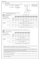
Pump section The pressurized oil outlet is always led to the main connection pedestal. Symbol for the basic hydraulic power pack valid only for pumps acc. to table 2a and 2b Order example: HK 34/1 - H5,1 - C5 3+230/400V 50 Hz Motor voltage HK 33/1 - Z2,7 - A1/120 3+230/400V 50 Hz Motor voltage High pressure radial piston pump with a delivery flow (flow corresponds to 3 pump cylinders) Codings for radial piston pump (high pressure pump) Delivery flow coding Geom. displacement Vg Delivery flow QPu No-load/load operation S6-10 min with approx. 30% LD Gear pump for low and mid range pressure applications....
Open the catalog to page 4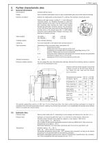
Further characteristic data General information Nomenclature Constant delivery pump Valve controlled radial piston pump or play compensated gear pump (with external toothing) Arbitrary for radial piston pumps (version H..), delivery flow direction remains the same. Versions with gear pumps ( coding Z... ) must rotate anti clockwise always. It is therefore necessary to check the rotation direction of the motor. The fan wheel has to rotate anti clockwise after starting the motor when looking through the perforation of the fan shroud. The connection of two of the three main wires has to be interchanged...
Open the catalog to page 5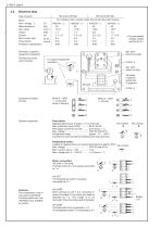
Electrical data Type of pump Motor Nom. voltage 1) Mains frequency Rev. rating Output Current Start current ratio Power factor Protection classification For 3-phase mains, 4-poles, stator shrunk into the pump housing (V) (Hz) (min-1) (kW) (A) (IA/IN) (cos ϕ) Terminals, if optional equipment is apparent Terminal box at the pump housing For permissible voltage ranges see section 5.1 ISO 1207M4x10-4.8-A2K For optional equipment see below M 20x1.5 ISO 1207M4x8-4.8-A2K Terminals, if optional equipment is apparent felt strip Customer furnished circuitry Mains 3 + 400V ! -connection (state of delivery)...
Open the catalog to page 6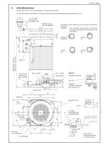
Unit dimensions All dimensions are in mm and are subject to change without notice! For the dimensions of the different connection blocks see the corresponding pamphlets listed in sect. 5.6 G 1 1/4 - filler neck reducer HK 34(33)../..M Additional cover with HK 34(33) R/.. Orientation of the upper part of the pump with terminal enclosure Attention: The 4 terminal box positions include the complete upper part (finned tube) and the oil level gauge. Port G 3/4 for auxiliary tank acc. to section 5.5 Installation example Silentbloc # 40x30 / M8 (65 Sh), also see sect. 5.4 Centering pin Breather Version...
Open the catalog to page 7All HAWE Hydraulik SE catalogs and technical brochures
 Pressure switch type DG 2025
21 Pages
 VR
VR15 Pages
 BVE
BVE54 Pages
 SLC
SLC17 Pages
 BNG
BNG25 Pages
 BA
BA45 Pages
 VB
VB88 Pages
 VP
VP35 Pages
 VH
VH6 Pages
 SL1
SL115 Pages
 ROLV
ROLV23 Pages
 EM
EM41 Pages
 PS
PS20 Pages
 K60N
K60N19 Pages
 V30D
V30D60 Pages
 V80M
V80M30 Pages
 V30E
V30E51 Pages
 RZ
RZ12 Pages
 Radial piston pump type R, RG
23 Pages
 C40V
C40V47 Pages
 Mini hydraulic power pack type A
23 Pages
 HR 080
17 Pages
 HICON
HICON14 Pages
 INKA
INKA35 Pages
 FXU
FXU35 Pages
 V60N
V60N71 Pages
 Product catalogue
299 Pages


