C40V
1 /47Pages

C40V
1 /47Pages
Catalog excerpts
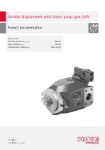
Variable displacement axial piston pump type C40V Product documentation Open circuit Nominal pressure pnom max: Peak pressure pmax: Displacement volume Vmax:
Open the catalog to page 1
© by HAWE Hydraulik SE. The reproduction and distribution of this document, as well as the use and communication of its contents to others without explicit authorization, is prohibited. Offenders will be held liable for the payment of damages. All rights reserved in the event of patent or utility model applications. Brand names, product names and trademarks are not specifically indicated. In particular with regard to registered and protected names and trademarks, usage is subject to legal provisions. HAWE Hydraulik respects these legal provisions in all cases. HAWE Hydraulik cannot provide individual...
Open the catalog to page 2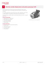
Overview variable displacement axial piston pump type C40V Variable displacement axial piston pumps adjust the geometric output volume from maximum to zero. As a result they vary the ow rate that is provided to the consumers. The variable displacement axial piston pump type C40V is designed for open circuits in mobile hydraulics and operates according to the swash plate principle. The range of pump controllers allows the axial piston pump to be used in a variety of applications. Features and advantages ■ Optimized power-to-weight ratio ■ Broad selection of controllers ■ Thru-shaft compatibility...
Open the catalog to page 4
Available versions Circuit symbol G 2.11 "Special versions and options" 2.10 "Pivoting angle of stops" Sensors Valves 2.9 "Thru-shaft" Gear pump Attachments 2.8 "Housing versions" 2.7 "Shaft journal" 2.6 "Flange versions (input side)" 2.5 "Rotation direction" 2.4 "Seals" Series version 2.2 "Controller" 2.3 "Solenoid voltage and version" 2.1 "Basic type and nominal size" 2.1 Basic type and nominal size Type Nominal pressure pnom (bar) Peak pressure pmax (bar)
Open the catalog to page 5
2.2 Controller Load-sensing controller Coding Load-sensing controller with integrated pressure limitation (Standard version for combination with hydraulic valves that relieve the LS signal in the valve, for example, type PSV proportional directional spool valve), see Chapter 2.2.1, "Load-sensing controllers LS0DA/LS2DA" Load-sensing controller with integrated pressure limitation and additional LS relief (only for use with hydraulic valves without their own relief of the LS signal), see Chapter 2.2.1, "Load-sensing controllers LS0DA/LS2DA" Load-sensing controller with electro-proportional pressure...
Open the catalog to page 6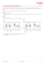
2.2.1 Load-sensing controllers LS0DA/LS2DA The LS0DA, LS2DA controllers are ow controllers that generate a variable, speed-independent ow rate. They adapt the displacement volume of the pump to the required ow rate of the consumer and regulate a constant difference between load pressure and pump pressure. The integrated pressure limitation restricts the maximum pressure to a set value. LS0DA ■ Connection X2-T sealed ■ Version for combination with hydraulic valves that relieve the LS signal in the valve, for example, type PSV proportional directional spool valve LS2DA ■ Connection X2-T open...
Open the catalog to page 7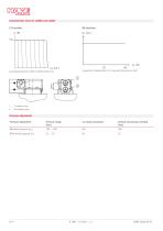
Characteristic lines for LS0DA and LS2DA LS function pB operating pressure (bar); Q delivery ow (%) Vg geometric displacement (%); pB operating pressure (bar) LS setting screw DA setting screw Pressure adjustment Pressure adjustment Factory-set pressure setting (bar) Maximum pressure pmax
Open the catalog to page 8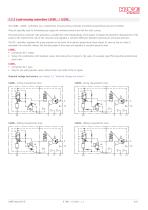
2.2.2 Load-sensing controllers LS0DE.. / LS2DE.. The LS0DE.. LS2DE.. controllers are a combination of load-sensing controller and electro-proportional pressure controller. They are typically used to simultaneously supply the working functions and the fan with a pump. The load-sensing controller (LS) generates a variable ow rate independently of the speed. It adapts the geometric displacement of the pump to the required ow rate of the consumer and regulates a constant difference between load pressure and pump pressure. The DE.. controller regulates the pump pressure on the basis of an electro-proportional...
Open the catalog to page 9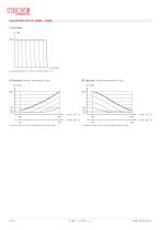
characteristic lines for LS0DE.., LS2DE.. LS function pB operating pressure (bar); Q delivery ow (%) DE function (rising characteristic line) DE function (falling characteristic line) I control current (mA); pB operating pressure (bar) I control current (mA); pB operating pressure (bar)
Open the catalog to page 10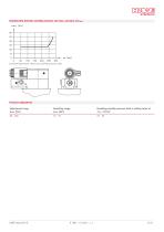
Relationship between standby pressure and max. pressure at Imax pB operating pressure (bar); pStby standby pressure (bar) Pressure adjustment Adjustment range pmax (bar) Resulting range pmin (bar) Resulting standby pressure with a setting value of Sp = 20 bar
Open the catalog to page 11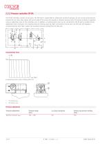
2.2.3 Pressure controller DF-DA The DF-DA controller consists of two parts. The ‘DA’ part is responsible for setting the maximum pressure. As soon as the pump pressure exceeds the set value, they reduce the swivel angle of the pump and regulate a constant pressure level. The pressure setting is adjusted using an adjusting screw on the controller, and, in addition, an external pilot valve can be connected to the X5 port to enable remote adjustment when necessary. If an external pressure-limiting valve has been connected to the X5 port, the ‘DF’ part will regulate a constant pressure level that...
Open the catalog to page 12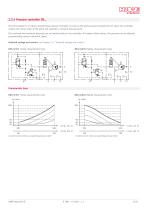
2.2.4 Pressure controller DE.. The DE controller is an electro-proportional pressure controller. As soon as the pump pressure exceeds the set value, the controller reduces the swivel angle of the pump and regulates a constant pressure level. The minimum and maximum pressures are set mechanically on the controller. In between these values, the pressure can be adjusted proportionally using an electrical signal. Solenoid voltage and version: see Chapter 2.3, "Solenoid voltage and version" DE1/3/5/7 (rising characteristic line) DE2/4/6/8 (falling characteristic line) Characteristic lines DE1/3/5/7...
Open the catalog to page 13
Relationship between standby pressure and max. pressure at Imax pB operating pressure (bar); pStby standby pressure (bar) Pressure adjustment Adjustment range pmax (bar) Resulting range pmin (bar) Resulting standby pressure with a setting value of Sp = 20 bar
Open the catalog to page 14All HAWE Hydraulik SE catalogs and technical brochures
 Pressure switch type DG 2025
21 Pages
 VR
VR15 Pages
 BVE
BVE54 Pages
 SLC
SLC17 Pages
 BNG
BNG25 Pages
 BA
BA45 Pages
 VB
VB88 Pages
 VP
VP35 Pages
 VH
VH6 Pages
 SL1
SL115 Pages
 ROLV
ROLV23 Pages
 EM
EM41 Pages
 PS
PS20 Pages
 K60N
K60N19 Pages
 V30D
V30D60 Pages
 V80M
V80M30 Pages
 V30E
V30E51 Pages
 RZ
RZ12 Pages
 Radial piston pump type R, RG
23 Pages
 Mini hydraulic power pack type A
23 Pages
 HR 080
17 Pages
 HICON
HICON14 Pages
 INKA
INKA35 Pages
 FXU
FXU35 Pages
 V60N
V60N71 Pages
 Product catalogue
299 Pages


