BVG 1
1 /13Pages

BVG 1
1 /13Pages
Catalog excerpts

2/2- and 3/2-way directional seated valves type BVG 1 and BVP 1 for any flow direction, zero leakage, all ports pressure resistant Pressure pmax = 400 bar = 20 lpm Flow Qmax Additional valves with same function o Type BVG 3, BVP 3 o Type NBVP 16 o Type BVE D 7400 (Qmax = 50 lpm, pmax = 315 bar) D 7765 N (Qmax = 20 lpm, pmax = 400 bar, NG 6) D 7921 (Qmax = 70 lpm, pmax = 400 bar, cartridge valve) General, brief description The 2/2- and 3/2-way directional valves type BVG 1 and BVP 1 are seated cone valves, which are available with solenoid, hydraulic, pneumatic, or manual actuation. All ports are equally pressure resistant, due to the internal pressure compensation. Valves featuring a spring return will return automatically into their idle position when not activated. The detented version will achieve its idle or working position after a brief impulse at the opposing solenoid. o Version for pipe connection o Version for manifold mounting o Version as double valve (distribution valve) HAWE Hydraulik SE STREITFELDSTR. 25 • 81673 MÜNCHEN © 1999 by HAWE Hydraulik Seated valves BVG(P) 1 September 20
Open the catalog to page 1
Available versions Type coding, main data BVP 1 R - WGM 230 BVG 1 Z - H - 3/8 BVG 1 R /B 1,1 - A - 1/4 Version as double valve (distribution valve) Type BVG 112 see sect. 5.3 Table 1: Basic type Flow Qmax (lpm) Coding Description Manifold mounting Pipe connection ISO 228/1 (BSPP) See dimensional drawing: Version with indiv. connection block, see sect. 5.2 Actuation, see table 4 on page 3 Table 2: Additional elements (for ports A, B, and C, see also section 3.1 „Flow limitation“) Additional element Additional element Table 3: Flow pattern symbols R With contact switch 250 bar applies to solenoid...
Open the catalog to page 2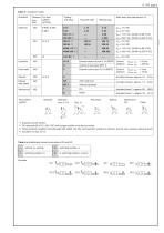
D 7765 page 3 Table 4: Actuation modes Actuation Pressure For flow pmax pattern (bar) symbols Coding with plug Main data, also see section 3.2 Plug with LED Without plug Control oil port (type BVP 1) External control oil port G 1/4 (BSPP) External control port G 1/4 (BSPP) Control: pcontr. min = 3 bar pressure pcontr. max = 15 bar Actuation torque: approx. 1.5 ... 3 Nm with hand lever Manual 400 with detent Control: pcontr. min = 24 bar pressure pcontr. max = 400 bar without handlever Actuation torque: approx. 1.5 ... 3 Nm Flow pattern symbol Actuation force: F = approx. 80 ... 190 N Actuation...
Open the catalog to page 3
Further characteristic data General and hydraulic data Installed position Overlap with 3/2-way directional valves Negative (overlap only apparent during transition from one to the other end position). All ports are interconnected during the switching process. Operating pressure According to table 4, sect. 2.1 Static overload capacity Ports A, B, and C approx. 2 x pmax Housing material and surface coating Steel, gas nitrided (basic valve) Mass (weight) approx. kg Complete with actuation Manual CD Without detent KD Pressure fluid Hydraulic oil conf. DIN 51514 part 1 to 3: ISO VG 10 to 68 conf....
Open the catalog to page 4
D 7765 page 5 Electrical data for contact switch Mech. service life Electr. service life (approx. cycles) Power supply 12 V DC, 5 A 24 V DC, 5 A To ensure save function the min. current specifications must be maintained; Imin (12 V DC) = 10 mA, Imin (24 V DC) = 100 mA Protection class (properly assembled) IP 65 (acc. to IEC 60529) Circuitry Idle position 1-3 Working position 1-2
Open the catalog to page 5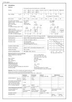
All solenoids are built and tested acc. to VDE 0580 Connection and circuitry Version G, GM, L, LM, WG, WGM: Plug conf. DIB EN 175 301-803 A All plugs For additional plugs, see D 7163 DC-voltage Type G... (applies also to the switches) Version G 24 EX: Cable cross section 3x0.5 mm2, Cable length 3 m, option 10 m (cable ÖLFLEX-440P ® Co. LAPP, D-70565 Stuttgart) On or Off: approx. 50...60 ms, 2-3 longer with WG approx. 2000, approximately evenly distributed Actuation pulse Protection class IP 65 (IEC 60529) (plug properly mounted) IP 67 (IEC 60529) with G 24 EX Insulation material class Contact....
Open the catalog to page 6
Unit dimensions All dimensions in mm, subject to change without notice! Valve section Version for pipe connection Switch (For missing data of the plug, see solenoid actuation section 4.2) Ports conf. ISO 228/1 (BSPP): A, B, and C = optional G 1/4 or G 3/8 Ports (BSPP) For dimension of the differing actuations, see section 4.2!
Open the catalog to page 7
D 7765 page 8 Version for manifold mounting Type BVP 1 R(S) Hole pattern manifold (view from top) Sealing of the ports via O-ring NBR 90 Sh 1): A, B = 7.65x1.78 Z = 2.54x1.78 Hole pattern manifold (view from top) Switch (For missing data of the plug, see solenoid actuation section 4.2) For missing data, see below! Hole pattern manifold (view from top) Sealing of the ports via O-ring NBR 90 Sh 1): A, B, C = 8.73x1.78 Z = 2.54x1.78 of seal kit DS 7765-1 (including O-rings for actuation H, H 1/4) 2) Port Z only with actuation coding H dimension of the differing actuations, see section 4.2!
Open the catalog to page 8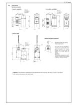
4.2 Actuations Electrical actuation Coding G... and WG... Manual emergency actuation Manual emergency actuation Manual emergency operation Manual emergency actuation Actuation aid (do not use any sharp-edged parts) The valve can be actuated, if required, by pushing the emergency actuation pin inward (visible from the top side) by means of a screw driver or similar. Attention: The pressure apparent at port B acts as a counter force resulting in approx. 195 N at 100 bar! Attention: This dimension is depending on the manufacturer and can be max. 40 mm acc. to EN 175 301-803 A. Both solenoid and...
Open the catalog to page 9
D 7765 page 10 Hydraulic actuation Pneumatic actuation Coding P Coding H (with BVP 1) Control port Z is located at the valve element (section 4.1!) Manual actuation Coding A Coding CD, KD Lock with CD (KD) 1(2, 3)
Open the catalog to page 10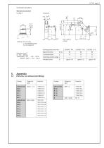
D 7765 page 11 Continuation actuations Mechanical actuation Coding T Safety lift mm play 1 mm operation travel 0.5 mm safety lift Working stroke (mm) with Actuation force F for 100 ... 400 bar: Type BVG(P) 1 R-T = 80 ... 140 N BVG(P) 1 Z(S)-T = 140 ... 190 N Switching position range s Functional travel Actuation force Parts No. for orifices (retrofitting) Coding without hole without hole without hole
Open the catalog to page 11All HAWE Hydraulik SE catalogs and technical brochures
 Pressure switch type DG 2025
21 Pages
 VR
VR15 Pages
 BVE
BVE54 Pages
 SLC
SLC17 Pages
 BNG
BNG25 Pages
 BA
BA45 Pages
 VB
VB88 Pages
 VP
VP35 Pages
 VH
VH6 Pages
 SL1
SL115 Pages
 ROLV
ROLV23 Pages
 EM
EM41 Pages
 PS
PS20 Pages
 K60N
K60N19 Pages
 V30D
V30D60 Pages
 V80M
V80M30 Pages
 V30E
V30E51 Pages
 RZ
RZ12 Pages
 Radial piston pump type R, RG
23 Pages
 C40V
C40V47 Pages
 Mini hydraulic power pack type A
23 Pages
 HR 080
17 Pages
 HICON
HICON14 Pages
 INKA
INKA35 Pages
 FXU
FXU35 Pages
 V60N
V60N71 Pages
 Product catalogue
299 Pages


