BVE
1 /54Pages

BVE
1 /54Pages
Catalog excerpts

Directional seated valve type BVE Product documentation Operating pressure pmax: Flow rate Qmax:
Open the catalog to page 1
© by HAWE Hydraulik SE. The reproduction and distribution of this document, as well as the use and communication of its contents to others without explicit authorization, is prohibited. Offenders will be held liable for the payment of damages. All rights reserved in the event of patent or utility model applications. Brand names, product names and trademarks are not specifically indicated. In particular with regard to registered and protected names and trademarks, usage is subject to legal provisions. HAWE Hydraulik respects these legal provisions in all cases. HAWE Hydraulik cannot provide individual...
Open the catalog to page 2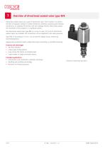
Overview of directional seated valve type BVE Directional seated valves are a type of directional valve. Their function is to direct the ow of hydraulic medium in certain directions, therefore connecting the relevant connections, or shutting off the ow with zero leakage. By this means they control the movement of the actuators in a hydraulic system. The directional seated valve type BVE is a screw-in valve. 2/2 and 3/2 directional seated valves are available. All connections can be subjected to the same pressures. Type BVE 1F according to D 7921 F can be used for highly viscous media (e.g....
Open the catalog to page 4
Available versions -B 2,5 2.6 "Orices/check valves (additional elements)" 2.5 "Single connection block" 2.4 "Actuating solenoid addition (type BVE 1 only)" 2.3 "Actuating solenoid" 2.2 "Circuit symbol" 2.1 "Basic type and size" 2.1 Basic type and size Type Flow rate Qmax (lpm) NOTICE Operating pressures depend on solenoid version see Chapter 3.1, "General data" NOTICE BVE 5 circuit symbol R only.
Open the catalog to page 5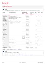
2.3 Actuating solenoid NOTICE The specifications regarding the IP protection class apply for versions featuring a properly assembled male connector. Coding Electrical connection Nominal voltage Coding X without plug Coding G with line connector MSD3-309 Coding L with LED plug Coding WG with alternating rectifier in line connector Coding 5k with cast-on cable 5 m long Coding .24/18W - if lower output required Details on operating pressures see Chapter 3.1, "General data" NOTICE For electrical connection according to ATEX: Observe electrical data for explosion-proof solenoids, see Chapter 3.5.1....
Open the catalog to page 6
NOTICE Solenoid for electrical connection according to ATEX in combination with connection blocks/sub-plates: When using a connection block that you have prepared yourself: The minimum volume of the connection block must not be undershot, see Chapter 3.5.1, "Electrical data for explosion-proof solenoids", page 19. Connection pattern G .., X .., L .., WG .. 2.4 Actuating solenoid addition (type BVE 1 only) Coding Without coding Blocking (circuit symbol R only) Manual operation, engaging Manual operation, not engaging (spring return mechanism) NOTICE Using blocking see Chapter 6.3.1, "Blocking...
Open the catalog to page 7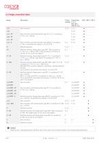
2.5 Single connection block Coding Circuit Connections symbols A, B, C ISO 228-1, ANSI B1.20.3 Pipe connection Pipe connection with thread position type VP 1 R, S, Z according to D 7915, pmax = 400 bar Pipe connection with thread position type GR(S)2-2 according to D 7300, not possible with solenoid ..X 24 EX 55 FM Manifold mounting Manifold mounting, ange pattern type BVP 1 R(S) according to D 7765, pmax = 400 bar, BVP 11 R(S) according to D 7400 up to 320 bar, do not use for new projects. Manifold mounting, ange pattern type VP 1 R, S, Z according to D 7915, pmax = 400 bar, type GR(S)2-12...
Open the catalog to page 8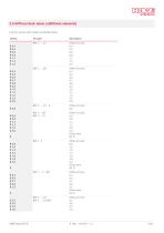
2.6 Orices/check valves (additional elements) only for version with single connection block. Coding B 0,4 B 0,5 B 0,6 B 0,8 B 1,1 B 1,3 B 1,5 B 0,4 B 0,5 B 0,6 B 0,7 B 0,8 B 0,9 B 1,0 B 1,1 B 1,3 B 1,5 B 2,0 B 0,8 B 0,6 B 0,8 B 1,1 B 1,3 B 1,5 B 2,0
Open the catalog to page 9
NOTICE Flow diagrams see Chapter 3.4, "Characteristic lines" HAWE Hydraulik
Open the catalog to page 10
3.1 General data Designation 2/2, 3/2-way directional seated valves Cone-seated valve Screw-in valve Steel; for BVE 1, 5: valve and coil housing, connection blocks with zinc-nickel coating for BVE 3: valve housing gas-nitrided, coil housing with zinc-nickel coating, connection blocks with zincnickel coating/galvanized Screw-in valve, on connection block for manifold mounting, pipe connection Overlap for 3/2-way directional valves Negative, transition from one ow direction to the other is completed only in the stroke end position. During switching, all ports are open to each other. Tightening...
Open the catalog to page 11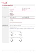
3.2 Pressure and volumetric ow Operating pressure pmax X 24 EX 55 FM Connection A, B, C BVE 1: 400 bar Flow rate Qmax X 24 EX 55 FM BVE 1: 20 lpm see Chapter 2.1, "Basic type and size" Static overload capacity approx. 2 x pmax, applies for valve in rest position Flow limit For accumulator circuits or when connected to high-pressure circuits with large pump delivery ow rates (ring lines, centralised supplies): Flow rates need to be limited according to system pressure – by orices to Qmax see Chapter 2.6, "Orices/ check valves (additional elements)", page 9. The orice must always be located...
Open the catalog to page 12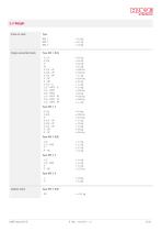
3.3 Weight Screw-in valve Single connection block Type BVE 1 R(S) - G 1/4 - G 3/8 -P - P1 - G 1/4 - VP - G 3/8 - VP - G 1/2 - VP - P - VP - P - BP - G 1/2 - G - 1/2 - NPTF - G - 1/4 - NPTF - 3/8 - NPTF - 1/4 - NPTF - VP - 3/8 - NPTF - VP - 1/2 - NPTF - VP Type BVE 5 R -1 -P Adapter plate
Open the catalog to page 13
3.4 Characteristic lines Viscosity of the hydraulic uid approx. 60 mm2/s Basic valve BVE 1 - Z C d A, C d B, A d C
Open the catalog to page 14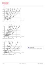
INFORMATION Orices 5.0 and 6.0 are estimated values!
Open the catalog to page 16
3.5 Electrical data Nominal power PN in the case of . 24/8W and WG... 2 - 3 times longer Switching operations approx. 2000/h, to be seen as approximately evenly distributed Contact temperature Insulation material class
Open the catalog to page 17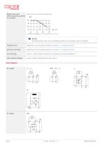
Relative duty cycle 100% duty cycle (specied on solenoid) Duty cycle as a function of temperature T Ambient temperature (°C); % duty cycle, T = 5 min NOTICE The thermal load of the coil can be reduced by means of an economy circuit, for example. Protection class Depending on the actuating solenoid see Chapter 2.3, "Actuating solenoid" Electrical connection Depending on the actuating solenoid see Chapter 2.3, "Actuating solenoid" Cut-off energy approx. < 1 Ws of reference value from measurements at nominal voltage UN other solenoid voltages Special voltages and plug options upon request Circuit...
Open the catalog to page 18All HAWE Hydraulik SE catalogs and technical brochures
 Pressure switch type DG 2025
21 Pages
 VR
VR15 Pages
 SLC
SLC17 Pages
 BNG
BNG25 Pages
 BA
BA45 Pages
 VB
VB88 Pages
 VP
VP35 Pages
 VH
VH6 Pages
 SL1
SL115 Pages
 ROLV
ROLV23 Pages
 EM
EM41 Pages
 PS
PS20 Pages
 K60N
K60N19 Pages
 V30D
V30D60 Pages
 V80M
V80M30 Pages
 V30E
V30E51 Pages
 RZ
RZ12 Pages
 Radial piston pump type R, RG
23 Pages
 C40V
C40V47 Pages
 Mini hydraulic power pack type A
23 Pages
 HR 080
17 Pages
 HICON
HICON14 Pages
 INKA
INKA35 Pages
 FXU
FXU35 Pages
 V60N
V60N71 Pages
 Product catalogue
299 Pages


