BNG
1 /25Pages

BNG
1 /25Pages
Catalog excerpts

Valve bank type BNG Product documentation Manifold mounting Operating pressure pmax: Flow rate Qmax:
Open the catalog to page 1
© by HAWE Hydraulik SE. The reproduction and distribution of this document as well as the use and communication of its contents to others without explicit authorisation is prohibited. Offenders will be held liable for the payment of damages. All rights reserved in the event of patent or utility model applications. Brand names, product names and trademarks are not specifically indicated. In particular with regard to registered and protected names and trademarks, usage is subject to legal provisions. HAWE Hydraulik respects these legal provisions in all cases. Printing date / document generated...
Open the catalog to page 2
Overview of valve bank type BNG A valve bank combines different valves for operating independent consumers. The directional valve bank type BNG consists of several valve sections, which are based on sub-plates. They can be used to flexibly assemble compact hydraulic manifolds. The valve bank type BNG can be flange-mounted directly on the hydraulic power packs. Features and benefits: ■ Sub-plates for flexible combination of directional valve types with NG 6 standard connection pattern Flange mount the valve bank directly onto the connection block of a hydraulic power pack. Can also be used as...
Open the catalog to page 4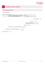
Available versions, main data 2.1 Order coding, overview Order coding example: BNG 2 NBVP 16 S NBVP 16 G B0,8R/ABR2,0/BBR1,5/A3B9/400/S NSWP 2 G B0,6R/ABR1,0/BBR1,5/50/S Additional elements at P and port assignment for A and B Sub-plate Directional valves and intermediate plates Connection block and additional elements at P Basic type and size
Open the catalog to page 5
2.2 Input section Table 1 Basic type and size Type Flow rate Qmax (lpm) Table 2 Connection block Coding Without coding No connection block in the event of direct mounting on the hydraulic power pack Terminator, ports sealed 2x P port and T port, optional check valve or orifice at P ( "Table 2a") Optional check valve or restrictor ( "Table 2a") Table 2a Additional elements at P Coding Without coding Check valve type RK 3 (D 7445) Orifice with orifice diameter Circuit symbol
Open the catalog to page 6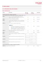
2.3 Valve sections 2.3.1 Directional valves and sub-plates Table 3 Directional valve Coding Flow rate Qmax (lpm) Directional valves NG 6, suitable for type BNG 2 Can be combined with intermediate plates type NZP in accordance with D 7788 Z NSWP 2 3/2, 3/3, 4/2 and 4/3 directional spool valve with additional options (pressure monitoring, restrictors and restrictor check valves in the ports) 3/3 and 4/3 directional spool valve Clamping module (combination of 4/2 or 4/3 directional spool valve, pressure reducing valve and tracked pressure switch) 2/2, 3/2 and 4/3 directional seated valves NOTE In...
Open the catalog to page 7
Table 3a Solenoid voltage Coding Electrical connection Nominal voltage DIN EN 175 301-803 A (Coding G... with line connector, coding L... with LED plug) (Coding WG with alternating rectifier in line connector) NOTE • The availability of additional solenoid voltages and solenoid versions is based on the directional valves used. • The solenoid voltages and solenoid versions are specified at the end of the valve bank and this applies to all solenoids. • The specifications regarding the IP protection class apply for versions featuring a properly assembled line connector. Electrical connection for...
Open the catalog to page 8
Table 4 Sub-plates Coding Series, 2x A and B port, optional check valve or orifice at P ( "Table 2a"), optional port assignment ( "Table 4a") Series connection, 2x A port and B port, the pressure resistance at the T port of the directional valve must be considered, optional check valve or orifice at P ( "Table 2a"), optional port assignment ( "Table 4a") Series, 3x A port and B port, optional check valve or orifice at P ( "Table 2a"), optional port assignment ( "Table 4a") Pressure reducing valve type ADM 33 P in the P channel, optional check valve or orifice at P ( "Table 2a")
Open the catalog to page 9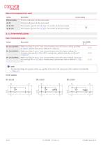
Table 4a Port assignment for A and B Coding Circuit symbol Without coding Ports A1 and B1 open; all other ports sealed Ports A2 and B2 open; all other ports sealed Filter elements type HFC 3/8 F (D 7235) in A1 and B1; all other ports sealed Filter elements type HFC 3/8 F (D 7235) in A2 and B2; all other ports sealed 2.3.2 Intermediate plates Table 5 Intermediate plates Coding ZPL 2/33/X/MVE6... Middle input block, P port or T port, pressure-limiting valve (with pressure setting) type MVE6 (D 7000/1), optional check valve or orifice at P ( "Table 2a") ZPL 2/33/S/MVE6... Middle input block, P port...
Open the catalog to page 10
2.4 End plates Table 6 End plates Coding S accumulator port, pressure-limiting valve (with pressure setting) type CMV 2 (D 7710 MV), drain valve, optional restrictor check valve ( "Table 6a") S accumulator port, component approved pressure-limiting valve (with pressure setting) type CMVX 2 (D 7710 TUV), drain valve, optional restrictor check valve ( "Table 6a") S accumulator port, prepared for CMV 2 or CMVX 2 (blocked), drain valve, optional restrictor check valve ( "Table 6a") optional restrictor check valve ( "Table 6a") Table 6a Restrictor check valve Coding Without coding Restrictor check...
Open the catalog to page 11
General Designation Valve bank Segment construction Manifold mounting DIN 50979-Fe ZnNi 8 Steel; nitrided valve housing, functional inner parts hardened and ground Installation position = Hydraulic oil inlets (pump) or hydraulic oil lead-on M, MP = measurement fittings Hydraulic fluid Hydraulic fluid: equivalent to DIN 51524-1 part 1 to 3; ISO VG 10 to 68 as per DIN ISO 3448 Viscosity range: min. approx. 4; max. approx. 400 mm2/s Also suitable for biologically degradable hydraulic fluids type HEPG (polyalkylene glycol) and HEES (synthetic ester). Cleanliness level Environment: approx. -20 to...
Open the catalog to page 12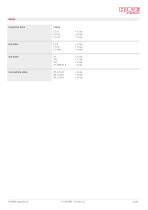
Weight Connection block Intermediate plates
Open the catalog to page 13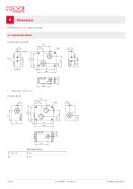
All dimensions in mm, subject to change. 4.1 Connection block Coding E 33 L, E 33 LX Tapped plugs in type E 33 LX
Open the catalog to page 14All HAWE Hydraulik SE catalogs and technical brochures
 Pressure switch type DG 2025
21 Pages
 VR
VR15 Pages
 BVE
BVE54 Pages
 SLC
SLC17 Pages
 BA
BA45 Pages
 VB
VB88 Pages
 VP
VP35 Pages
 VH
VH6 Pages
 SL1
SL115 Pages
 ROLV
ROLV23 Pages
 EM
EM41 Pages
 PS
PS20 Pages
 K60N
K60N19 Pages
 V30D
V30D60 Pages
 V80M
V80M30 Pages
 V30E
V30E51 Pages
 RZ
RZ12 Pages
 Radial piston pump type R, RG
23 Pages
 C40V
C40V47 Pages
 Mini hydraulic power pack type A
23 Pages
 HR 080
17 Pages
 HICON
HICON14 Pages
 INKA
INKA35 Pages
 FXU
FXU35 Pages
 V60N
V60N71 Pages
 Product catalogue
299 Pages


