Subminiature D Connectors
1 /200Pages

Subminiature D Connectors
1 /200Pages
Catalog excerpts

D-Sub connectors are an Industry Standard for cable-to-board connectivity applications. Thanks to the large variety of solutions it offers, it can be universally used as a device interface. Our customers manufacturing requirements are addressed by the comprehensive range of PCB termination styles available. It is particularly suited to configuring communication and data interfaces and is the standard for many fieldbus profiles. Solutions for the cable connector that can be easily assembled in the field are available for automation applications. Cable/ Wire to Board high performance Power Data transfer rate Cage clamp Axial screw Number of contacts, contact density Voltage, working current Application standard HanQuick Lock® Housing integration Separate housing Integrated hous
Open the catalog to page 1
05. Subminiature D Connectors Contents D-Sub Standard connectors (D-Sub – S) . . . . . . . . . . . . . . . . . . . . . . . . . . . . . . . . . . . . . . D-Sub High Density connectors (D-Sub – HD) . . . . . . . . . . . . . . . . . . . . . . . . . . . . . . . . . . D-Sub Mixed connectors (D-Sub – M) . . . . . . . . . . . . . . . . . . . . . . . . . . . . . . . . . . . . . . . . D-Sub Filter connectors (D-Sub – F) . . . . . . . . . . . . . . . . . . . . . . . . . . . . . . . . . . . . . . . . . D-Sub Waterproof IP67 connectors (D-Sub – W) . . . . . . . . . . . . . . . . . . . . . . . . . . . . ....
Open the catalog to page 2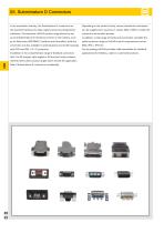
05. Subminiature D Connectors In the automation industry, the Subminiature D connectors are Depending on the product family, various termination techniques the standard interfaces for data, signal and service/programmer can be supplied such as press-in, solder, SMC or SMT to match the interfaces. The extensive HARTING product range allows the set customer’s termination process. up of all Subminiature D interfaces common in the industry, such In addition, a wide range of hoods and accessories complete the as for field buses (PROFIBUS, CanOpen and DeviceNet), while the cable connector range to...
Open the catalog to page 3
Specific features of the product range D-Sub – Mixed connectors with nearly 20 different contact arrangements offering versatile options for mixing power, coaxial, high voltage, signal and even pneumatic contacts in one connector. D-Sub – Waterproof IP65 / IP67 connectors with 9 to 50 contacts for panel mount to PCB or cable. D-Sub – Filter connectors with 9 to 37 contacts and integrated, different filter designs, like C, L or Pi types. D-Sub – High Density connectors with 15 to 78 straight and right-angled contacts, exceeding the contact capacity of the standard Subminiature D connectors by...
Open the catalog to page 4
Technical characteristics Number of contacts 9, 15, 25, 37, 50 UL recognized Working current see current carrying capacity chart Current carrying capacity The current carrying capacity is limited by maximum temperature of materials for inserts and contacts including terminals. The current capacity-curve is valid for continuous, not interrupted current-loaded contacts of connectors when simultaneous power on all contacts is given, without exceeding the maximum temperature. Control and test procedures according to DIN IEC 60 512. Example: 25 way connector © Turned contacts © Stamped contacts...
Open the catalog to page 5
Turned solder pins, straight D-Sub Identification Performance levels Explanations see page 05.04 Other performance levels on request Male connector metal shell with dimples Female connector metal shell Male connector Female connector Board drillings Part number Performance level Performance level 1) Not normally kept in stock Mating conditions see page 05.04
Open the catalog to page 7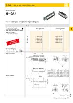
Part number Performance levels Explanations see page 05.04 Other performance levels on request Male connector Performance level metal shell with dimples Please insert digit for flange thread or fitted M3 ► 1 fe male screw locks 4-40 UNC ► 2 fitted screw locks 4-40 UNC ► 3 Male connectorBoard drillings fitted screw locks 4-40 UNC X 05 07 Mating conditions see page 05.04
Open the catalog to page 8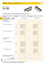
9--50 Stamped solder pins, straight with/without grounding board locks Identification D-Sub Performance levels Part number Performance level Explanations see page 05.04 Other performance levels on request Performance level Male connector metal shell with dimples Without grounding board locks W ith grounding board locks Female connector metal shell Without grounding board locks W ith grounding board locks Please insert digit for flange thread or fitted female screw locks þ 1 M3 4-40 UNC þ 2 1) fitted screw locks 4-40 UNC þ 3 Fitted screw locks 4-40 UNC not normally kept in stock for performance...
Open the catalog to page 9
D-Sub DIN 41652 ■ CECC 75 301-802 Number of contacts Male connector 9 - 37 contacts Female connector 9 - 37 contacts Board drillings 9 - 37 contacts
Open the catalog to page 10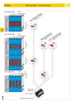
D-Sub Front panel width Mounting details – angled solder pins Front panel width Metal shell mating face Fixed contacts Front panel width Integrated mounting bracket
Open the catalog to page 11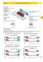
Mounting details – angled solder pins Advantages All-round protective metal shell • olarisation P • ontact protection C • lated shell P • ale connector with M dimples Contact surface finish to different performance levels Plated terminations for increased solderability Different metal threads possible in flange area • 3 M • -40 UNC 4 • itted female screw locks f 4-40 UNC • ax. torque ≤ 0.8 Nm m Grounding contact riveted to metal shell Integrated plastic mounting bracket Mounting bracket Mounting bracket with snap-in-clips and grounding pin Mounting height Low-Profile Versions The reduced mounting...
Open the catalog to page 12
Mounting height Standard Versions Turned solder pins, angled with/without snap-in-clips and grounding board locks Identification Performance levels Part number Performance level Performance level Explanations see page 05.04 Other performance levels on request Male connector metal shell with dimples W ith snap-in clips and grounding board locks lable avai quest on re Without snap-in clips and grounding board locks lable avai quest on re Please insert digit for flange thread or fitted female screw locks þ 1 M3 4-40 UNC þ 2 fitted screw locks 4-40 UNC þ 3
Open the catalog to page 13All HARTING catalogs and technical brochures
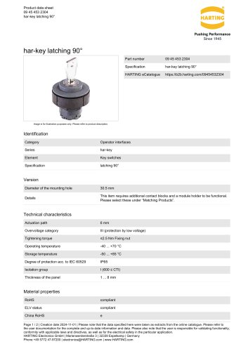 09 45 453 2304
2 Pages
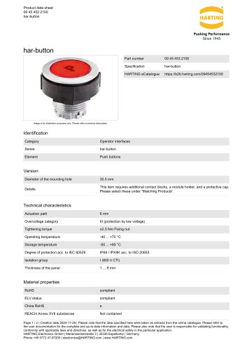 09 45 453 2100
2 Pages
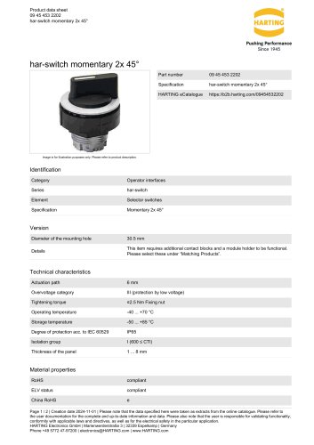 09 45 453 2202
2 Pages
 Ha-VIS RFID4SMT
2 Pages
 Ha-VIS eCon 2050GX-I-A
3 Pages
 Ha-VIS eCon 3000
2 Pages
 Han-Modular® Switch US4
2 Pages
 STAF 6 STI-L
2 Pages
 Han 3A-eg-QB-PG-13.5
2 Pages
 SEK IDC Connectors
54 Pages
 Industrial Connectors Han®
52 Pages
 livebook
10 Pages
 HA-CheckOut® EK HE RL
2 Pages
 M12 Magnetics
1 Page
 M8 D-coded PCB adapter
1 Page
 Han® Pneumatic Module Metal
2 Pages
 Han-Modular® Sliding Frame
2 Pages
 HARTING Device Connectivity_2016
896 Pages
 HARTING Connectors DIN 41 612
230 Pages
 Coaxial and Metric Connectors
128 Pages
 HARTING Industrial Connectors han®
989 Pages
 Ha-VIS RFID RF-R300 Reader
4 Pages
 HARTING Component Range
40 Pages
 HARTING News 2016
120 Pages
 The Future needs the Past
11 Pages
 HIS Catalogue
32 Pages
 HIS Flyer
12 Pages


Archived catalogs
 HARTING Device Connectivity
824 Pages
 TCA Connectors
36 Pages
 Industrial Connectors (Han®)
33 Pages
- HARTING data connector
- Transformer
- Rectangular housing
- HARTING electrical power supply connector
- Ethernet switch
- Copper cable
- Metal connector
- Industrial network switch
- Round connector
- HARTING plastic connector
- Plastic housing
- Industrial connector
- Screw-in connector
- Gigabit ethernet switch
- Junction block
- Circular connector
- Rectangular connector