HARTING Device Connectivity - har-link® Interface Connectors
1 /54Pages

HARTING Device Connectivity - har-link® Interface Connectors
1 /54Pages
Catalog excerpts

SEK connectors for flat cables enable simple and -, cost-optimized device configuration. SEK connectors are preferably used for connection within the device. HARTING offers a broad range of these cable-to-board connectors. Assembly on the cable side takes place in one work step for all contacts via flat conductors. The SEK is an economical and reliable interface for data and signal applications in industry. Data Signal Power Cable termination Data transfer rate
Open the catalog to page 1
SEK connector system – introduction . . . . . . . . . . . . . . . . . . . . . . . . . . . . . . . . . . . . . . . . . General information . . . . . . . . . . . . . . . . . . . . . . . . . . . . . . . . . . . . . . . . . . . . . . . . . . . . . . Solder board connectors . . . . . . . . . . . . . . . . . . . . . . . . . . . . . . . . . . . . . . . . . . . . . . . . . . Male standard connectors . . . . . . . . . . . . . . . . . . . . . . . . . . . . . . . . . . . . . . . . . . . . . . . Male low-profile conncectors . . . . . . . . . . . . . . . . . . . . . . . . . . . . . . . . . . . . . . . . ....
Open the catalog to page 2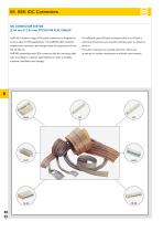
08. SEK IDC Connectors IDC connector system [2.54 mm x 2.54 mm pitch] for flat cables HARTING ’s product range of flat cable connectors is designed for The different types of board connectors offer 6 to 64 pins in various cable-to-PCB applications. The HARTING SEK insulation various terminations such as solder (manual, wave or reflow) or displacement connector technology meets all requirements of the The cable connectors are equally suited for indoor use HARTING assembles each SEK connector with the matching cable as well as for outdoor applications and harsh environments. type according to customer...
Open the catalog to page 3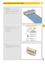
Specific features of the product range Cable assemblies • ARTING can supply cable assemblies according to your H specifications. • wide range of connector types available with various contact A arrangements constitute the ideal solution to your wiring problems. General information • ables of all types in economic reel lengths are available. C • ables professionally assembled on HARTING work stations C ensure reliable connections. • inished harnesses are subject to 100% quality checks on a F HARTING test device. • nsulation test by 1000 V. I • ontact resistance test. C Economy • he tested assembly...
Open the catalog to page 4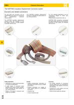
General information The HARTING Insulation Displacement Connector system Economic and reliable connections The flat cable and connector can be preassembled and used as a component with predetermined functional characteristics. The HARTING insulation displacement technique constitutes the ideal solution to your wiring problems. The HARTING insulation displacement contacts pierce the insulation on the flat cable to provide a durable gastight connection with the wire. HARTING SEK connectors incorporate the latest design features and rovide the p assurance of high quality and eliability r with...
Open the catalog to page 5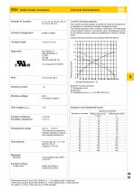
Contact arrangement straight, angled Current carrying capacity The current carrying capacity is limited by maximum temperature of materials for inserts and contacts including terminals. The current capacity-curve is valid for continuous, not interrupted current-loaded contacts of connectors when simultaneous power on all contacts is given, without exceeding the maximum temperature. Control and test procedures according to DIN IEC 60 512. Working current Example: 50 way connector © Temperature rise © Derating © Derating curve at Imax. x 0.8 (IEC 60 512-2) Working voltage 500 V for pollution degree...
Open the catalog to page 6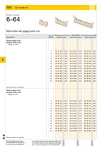
SEK IEC 60 603-13 Number of contacts Identification contacts Without levers With short levers With long levers Male header with angled solder pins Length: 2.9 mm Kinked version on request Male header with angled solder pins Length: 4.5 mm Kinked version on request * Not normally kept in stock For accessories see page 08.16 For dimensions see page 08.07 For performance level 3 please specify digit For performance level 2 please specify digit S4 = 0.76 pm (30 pinch) Au or PdNi eqivalent
Open the catalog to page 7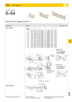
6--64 Male header with angled solder pins Drawing Male header Short levers for use with female connector without strain relief clamp Long levers for use with female connector with strain relief clamp a) Solder pins for 1 ± 0.1 mm dia. hole Marking No. 1 contact No. 1 contact Board drillings N o polarization slot for 6, 10 or 14 way male header N o polarization slot for 6 way male header P itch tolerance: ± 0.1
Open the catalog to page 8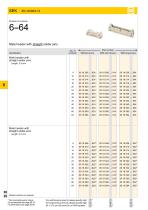
08 08 SEK IEC 60 603-13 Number of contacts Male header with straight solder pins No. of <- Part number -► Identification contacts Without levers With short levers With long levers Male header with straight solder pins Length: 2.9 mm Male header with straight solder pins Length: 4.5 mm Kinked version on request * Not normally kept in stock For accessories see page 08.16 For dimensions see page 08.09 For performance level 3 please specify digit For performance level 2 please specify digit S4 = 0.76 pm (30 pinch) Au or PdNi eqivalent
Open the catalog to page 9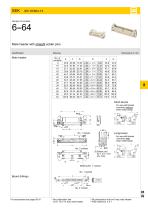
Male header with straight solder pins Identification Short levers is Long levers for use with female connector with strain relief clamp Board drillings 1) No polarization slot for 6, 10 or 14 way male header 2) No polarization slot for 6 way male header 3) Pitch tolerance: ± 0.1
Open the catalog to page 10
SEK IEC 60 603-13 Number of contacts Identification contacts Without levers With short levers With long levers Male header with straight solder pins, kinked Length: 2.9 mm 08 10 * Not normally kept in stock For accessories see page 08.16 For dimensions see page 08.11 For performance level 3 please specify digit For performance level 2 please specify digit S4 = 0.76 pm (30 pinch) Au or PdNi eqivalent
Open the catalog to page 11
6--64 Male header with straight solder pins, kinked Drawing Male header Short levers for use with female connector without strain relief clamp Long levers for use with female connector with strain relief clamp Marking No. 1 contact No. 1 contact Board drillings No. 2 contact l inked contact: pcb thickness from 1.50 to 1.94 mm after Cu + Sn plating with K non-remelted through holes ø 0.80 to ø 0.95 mm. Max. insertion force = 125 N. Min. retention force = 3 N. Non-kinked contact: Solder pins for pcb connections ø 1 ± 0.1 mm as per IEC 60 603-13. For accessories see page 08.16 N o polarization slot...
Open the catalog to page 12All HARTING catalogs and technical brochures
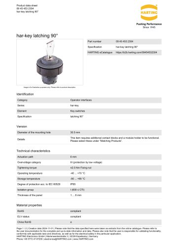 09 45 453 2304
2 Pages
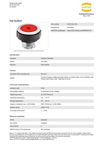 09 45 453 2100
2 Pages
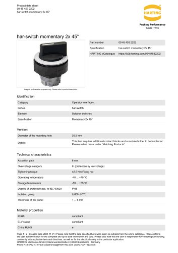 09 45 453 2202
2 Pages
 Ha-VIS RFID4SMT
2 Pages
 Ha-VIS eCon 2050GX-I-A
3 Pages
 Ha-VIS eCon 3000
2 Pages
 Han-Modular® Switch US4
2 Pages
 STAF 6 STI-L
2 Pages
 Han 3A-eg-QB-PG-13.5
2 Pages
 SEK IDC Connectors
54 Pages
 Subminiature D Connectors
200 Pages
 Industrial Connectors Han®
52 Pages
 livebook
10 Pages
 HA-CheckOut® EK HE RL
2 Pages
 M12 Magnetics
1 Page
 M8 D-coded PCB adapter
1 Page
 Han® Pneumatic Module Metal
2 Pages
 Han-Modular® Sliding Frame
2 Pages
 HARTING Device Connectivity_2016
896 Pages
 HARTING Connectors DIN 41 612
230 Pages
 Coaxial and Metric Connectors
128 Pages
 HARTING Industrial Connectors han®
989 Pages
 Ha-VIS RFID RF-R300 Reader
4 Pages
 HARTING Component Range
40 Pages
 HARTING News 2016
120 Pages
 The Future needs the Past
11 Pages
 HIS Catalogue
32 Pages
 HIS Flyer
12 Pages


Archived catalogs
 HARTING Device Connectivity
824 Pages
 TCA Connectors
36 Pages
 Industrial Connectors (Han®)
33 Pages
- HARTING data connector
- Transformer
- Rectangular housing
- HARTING electrical power supply connector
- Ethernet switch
- Copper cable
- Metal connector
- Industrial network switch
- Round connector
- HARTING plastic connector
- Plastic housing
- Industrial connector
- Screw-in connector
- Gigabit ethernet switch
- Junction block
- IP67 connector
- Circular connector
- Rectangular connector