07. har-link® Interface Connectors
1 /8Pages

07. har-link® Interface Connectors
1 /8Pages
Catalog excerpts

07. har-link ® Interface Connectors The highest data rates in combination with perfect shielding characterize the har-link® connector. This way data can be passed on optimally within the control cabinet. The locking mechanism ensures a vibration-proof connection and easy-to-install handling at a minimum size and maximum options for combination with other units. HARTING offers assembled system cables with shielded or unshielded twisted pairs for the har-link® connector family. Cable/ Wire to Board high performance Power Data transfer rate Cage clamp Axial screw Number of contacts, contact density Voltage, working current Application standard HanQuick Lock® Housing integration Separate housing Integrated hous
Open the catalog to page 1
07. har-link ® Interface Connectors Contents connector system – general information . . . . . . . . . . . . . . . . . . . . . . . . . . . . . . . . Technical characteristics . . . . . . . . . . . . . . . . . . . . . . . . . . . . . . . . . . . . . . . . . . . . . . . . . . . Male and female connectors . . . . . . . . . . . . . . . . . . . . . . . . . . . . . . . . . . . . . . . . . . . . . . . Accessories and cable assemblies . . . . . . . . . . . . . . . . . . . . . . . . . . . . . . . . . . . . . . . . . . . connector system – introduction . . . . . . . . . . . . . . . . . . . . . . . . . ....
Open the catalog to page 2
07. har-link ® Interface Connectors Metric har-link® interface connectors in 2.0 mm pitch therefore perfectly suited for modern transmission protocols such as Low Voltage Differential Signals (LVDS). requirements of IEC 61076-4-107 and is a compact and robust The thorough EMI shielding of the har-link® connector is a PCB-to-cable interface with excellent data transmission properties. guarantee of its superior performance in the EMI-polluted All dimensions of the har-link® connector are in accordance with IEC 917 and IEEE P 1301 specifications, allowing an easy The high temperature resistant material...
Open the catalog to page 3
Specific features of the product range • Data transmission up to 2 Gbit/s • s perfectly suited for modern transmission protocols such as I Low Voltage Differential Signals (LVDS) • A screening attenuation of more than 50 dB up to 1 GHz • he high temperature resistant material of the female T har-link® connector supports reflow soldering • Shielding with integrated locking levers • ue to the locking levers on both sides of the male connector, the D connection withstands a pulling force up to 8
Open the catalog to page 4
connector system The connector system of HARTING complies with the requirements of IEC 61 076-4-107 and is a compact and robust pcb-to-cable interface with e xcellent data transmission properties for high-speed net orking and telecommunications. w All dimensions of the connector are in accorr dance with IEC 917 and IEEE P 1301 equirements, which allows for easy implementation nto both etric i m supports and inch-based systems. In addition, hot plugging as required by modern bus ystems s such as CompactPCI, S-bus and VME. allows data transmission up to 2 Gbit/s per pair and is therefore...
Open the catalog to page 5
Technical characteristics Number of contacts 10 Approvals IEC 61076-4-107 Contact pitch 2 mmConnector pitch 6 mm Working current 1.5 a at 70 oc Test voltage Ur.m.s. 750 V Contact resistance < 35 mQInsulation resistance > 1010 q har-link Temperature range during reflow soldering Mating cycles 250, performance level 2 Terminations Insulation displacement (male), AWG 28/7 - 30/7, AWG 30 solid Solder pins for 0 0.6 mm min. (female) Insertion force Withdrawal force 10 N max. / module 2 N min. / module (without locking levers)Latching system Locking levers Materials Mouldings...
Open the catalog to page 6
Male connectors, straight Female connectors, angled Identification Part number Female connector with solder pins har-link Male connector for insulation displacement 10 Red 10 Yellow 10 Green 10 Blue 10 Black Male connector (delivered in piece parts) Manuals for the har-link ® cable free connector assemblies are available on demand. Please contact your local HARTING representative. Female connector Shielding pins Shielding pins date code Nipple location Dimensions [mm] Tooling see chapter 20
Open the catalog to page 7
Identification Bracket with four cavities har-link Gasket with four cavities Standard har-link® cable assembly Cable: 5 twisted pairs, AWG 28, shielded, PVC Wiring: 1:1 High end har-link® cable assembly Cable: 5 twisted pairs, AWG 30, double shielded, PVC Wiring: 1:1 Cable: 5 twisted pairs, AWG 30, double shielded, PVC Wiring: acc. to IEEE 1355
Open the catalog to page 8All HARTING catalogs and technical brochures
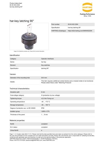 09 45 453 2304
2 Pages
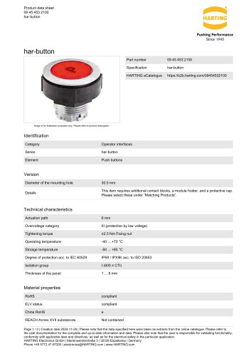 09 45 453 2100
2 Pages
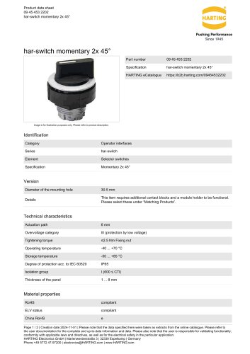 09 45 453 2202
2 Pages
 Ha-VIS RFID4SMT
2 Pages
 Ha-VIS eCon 2050GX-I-A
3 Pages
 Ha-VIS eCon 3000
2 Pages
 Han-Modular® Switch US4
2 Pages
 STAF 6 STI-L
2 Pages
 Han 3A-eg-QB-PG-13.5
2 Pages
 SEK IDC Connectors
54 Pages
 Subminiature D Connectors
200 Pages
 Industrial Connectors Han®
52 Pages
 livebook
10 Pages
 HA-CheckOut® EK HE RL
2 Pages
 M12 Magnetics
1 Page
 M8 D-coded PCB adapter
1 Page
 Han® Pneumatic Module Metal
2 Pages
 Han-Modular® Sliding Frame
2 Pages
 HARTING Device Connectivity_2016
896 Pages
 HARTING Connectors DIN 41 612
230 Pages
 Coaxial and Metric Connectors
128 Pages
 HARTING Industrial Connectors han®
989 Pages
 Ha-VIS RFID RF-R300 Reader
4 Pages
 HARTING Component Range
40 Pages
 HARTING News 2016
120 Pages
 The Future needs the Past
11 Pages
 HIS Catalogue
32 Pages
 HIS Flyer
12 Pages


Archived catalogs
 HARTING Device Connectivity
824 Pages
 TCA Connectors
36 Pages
 Industrial Connectors (Han®)
33 Pages
- HARTING data connector
- Transformer
- Rectangular housing
- Ethernet switch
- HARTING electrical power supply connector
- Metal connector
- Copper cable
- Industrial network switch
- Round connector
- HARTING plastic connector
- Plastic housing
- Screw-in connector
- Industrial connector
- Gigabit ethernet switch
- Junction block
- Circular connector
- IP67 connector
- Rectangular connector