
- Catalogs
- Hansheng Automation (Dongguan) Co., Ltd.
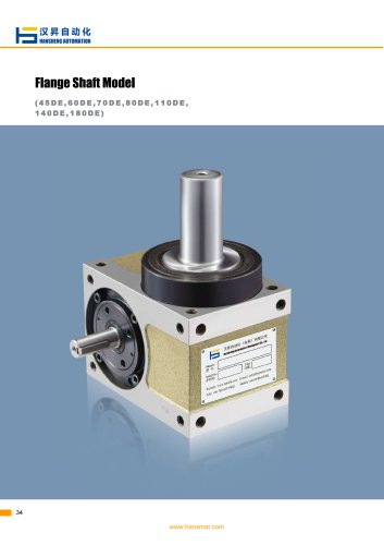
- Intermittent indexer 80DFH

Intermittent indexer 80DFH
Intermittent indexer 80DFH
This document provides a comprehensive guide on the Cam Indexing Table by Hansheng Automation, detailing its working mechanism, specifications, maintenance, and model selection.
1. How Cam Indexer Works:
The cam indexer uses a globoidal cam on the input shaft interacting with a turret on the output shaft. The cam follower ensures smooth motion, with adjustments available to eliminate backlash and enhance rigidity.
2. Specifications and Mechanism Principle:
Key terms include indexing cam, drive angle, dwell angle, and torque. The document emphasizes smooth motion curves to minimize vibration and noise, highlighting acceleration and jerk's role in indexing accuracy.
3. Motion Diagrams and Curves:
Discusses motion curves like discontinuous, double stationary symmetric, and asymmetric curves, affecting velocity, acceleration, and jerk, impacting performance and load capacity.
4. Types of Drives:
Describes indexing, oscillating, and roller drives, each with specific operational characteristics. Indexing drives operate intermittently, oscillating drives allow bidirectional rotation, and roller drives offer stable rotation without backlash.
5. Model Selection and Assembly:
Guidelines for model selection based on torque load calculations are provided, along with assembly notices emphasizing smooth input shaft rotation to prevent overload.
6. Maintenance and Lubrication:
Regular maintenance, including lubricant changes, is crucial for longevity and accuracy. The document warns against mixing lubricants and stresses eliminating backlash.
7. Safety and Overload Protection:
Overload protection devices are essential to prevent damage and ensure safety, with torque limiters recommended for maintaining normal operation.
Specifications and Maintenance:
Safety devices prevent follower breakage, with regular checks every 5000 hours. Proper lubrication is crucial, with annual lubricant replacement recommended.
Lubrication Guidelines:
Viscosity should be based on speed, using Petro China #90 oil with additives. Avoid mixing lubricants and replace them after initial 500-1000 hours, then every 3000 hours.
Table Installation and Torque Specifications:
Table size should match output torque load, with high precision requiring 2-3 times the torque. Maximum table diameter should be five times less than the nominal dimension.
Cam Curve Selection:
Cam curve impacts accuracy and life, with options like modified sine, trapezoid, and constant velocity. Selection depends on speed and load conditions.
Use Examples and Calculations:
Examples for applying sub-tables and driving conveyors include calculations for inertia, friction, and loading torque, with safety factors and efficiency considerations.
Ordering and Model Specifications:
Model codes specify cam and turret assembly, output, input, and mounting positions, with options for right or left-hand cams and various motion curves.
Technical Parameters:
Allowable loads and torque on input and output shafts are specified, along with indexing accuracy and weight considerations.
Data Interpretation:
Tables and charts provide critical data on torque and load capacities, essential for ensuring mechanical components operate within safe and efficient parameters. Adhering to specified values is emphasized to maintain system integrity and performance.
Catalog excerpts

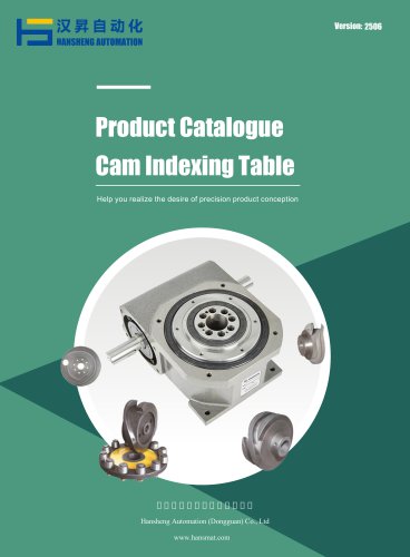
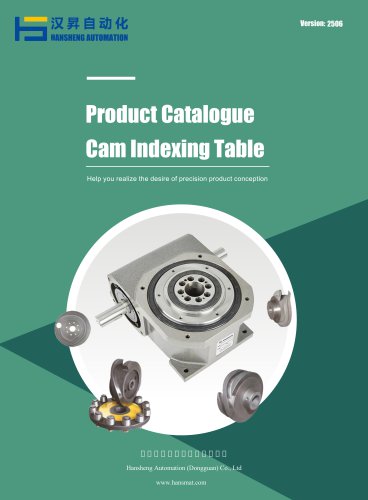
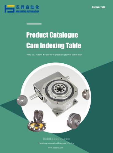
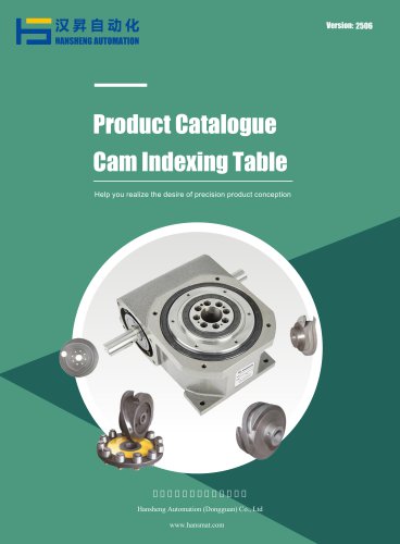
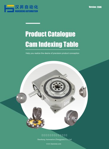
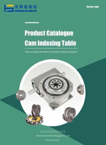
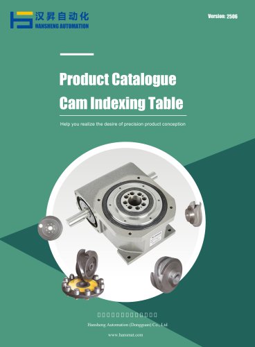
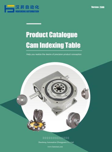
Product Catalogue Cam Indexing Table 汉昇自动化(东莞)有限公司 Hansheng Automation (Dongguan) C
Open the catalog to page 1
Order Code----------------------------------------------------------------------- DE Flange Shaft Model ----------------------------------------------------- DA Ultra-thin Table Model -------------------------------------------------
Open the catalog to page 2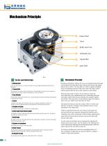
Mechanism Principle Output Shaft Turret Roller Gear Cam Globoidal Cam Tapered Rib Input Shaft Mechanism Principle Terms and Definition 1. Indexing Cam A cam in which a groove is cut into the surface of a drum-shaped solid body and fixed to the input shaft. 2. Tapered Rid The tapered rib is located on the circumference of the globoidal cam, between the cam grooves, coming into linear contact with the circumference of the cam follower. 3. Cam follower: This precision-designed cam follower use a needle bearing developed by Hansheng and designed to withstand heavy loads. 4. Turret Attached to the...
Open the catalog to page 3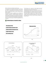
There are countless curves connecting two points in space. This is also true of the motion diagrams used for index drives, where there are innumerable curves connecting the starting point with the ending point. However, when designing a motion in indexing, it is necessary to use a curves as smooth as possible. To this end, vibration, noise and rigidity of materials should be taken into account. Also load and speed should be considered. After all factors are taken into consideration, curves emphasizing the characteristics of the speed, acceleration and jerk are usually used. Acceleration, especially...
Open the catalog to page 4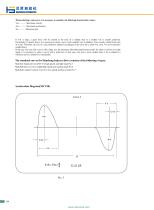
If Vm is large, a great force will be exerted at the time of a sudden stop so a smaller Vm is usually preferred. Particularly if a load is heavy, it is necessary to select a curve with a smaller Vm. In addition, Vm is closely related to the size of a cam. Therefore, the size of a cam should be reduced accordingly if the curve has a small Vm. Also, Vm never becomes smaller than 1. In the case of a cam with a curve with a large Am, the maximum allowable load becomes small. So when it is driven at a high speed, it is necessary to select a curve with a small Am. In this case,, the Am is never smaller...
Open the catalog to page 5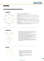
Overview Indexing Drives/Oscillating Drives/Roller Drives Indexing Drives • The indexing drives operate intermittently as follows: Dwell→AE Index→AE Dwell→AE Index. • Dwell: Output shaft stops rotating and cam follower touches the straight part of taper rib of roller gear cam. • Index: Output shaft rotates and cam follower touches the curve part of taper rib of roller gear cam. • Usually, the indexing drives dwells for a moment after input shaft rotates once and then output shaft indexes once. • After output shaft rotates, the indexing drives dwell. At this moment, the operators can decide the...
Open the catalog to page 6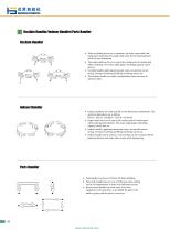
Oscilate Handler/Indexer Handler/Parts Handler Oscilate Handler • When oscillating drives are in operation, the rotary input shaft with equal speed shall make the output shaft rotate forward and backward and lift in two dimensions. • The output shaft can be set to stop at the central point of rotation path while oscillating. The rotary angle degree and lifting capacity can be also set. • Oscillate handler, applying stereoscopic cams, can provide correct timing. Overlap of rotating and lifting and timing can be set. • The oscillate handler can make a transportation from conveyor to operation table....
Open the catalog to page 7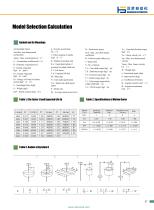
Model Selection Calculation J Symbol and Its Meanings Am:Max. non-dimensional acceleration Ee : Energy of a body for linear motion (kgf - m - s-2) I : Polar moment of inertia (kgf - m - s2) K e : Equivalent radius of gyration for output shaft (m) L f : Lift factor L h : Expected life (hr) N o : Initial cam shaft speed (rpm) Pa : Average motor power (kw) Ps : Peak motor power Q m : Max. cam shaft torque coefficient R : Follower pitch radius (m) r : Speed ratio S : No. of station T c : Cam shaft torque (kgf - m) T d : Start/stop torque (kgf - m) T f : Friction torque (kgf - m) T t : Total torque...
Open the catalog to page 8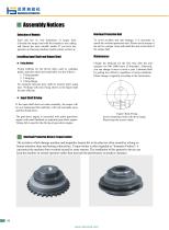
Assembly Notices Selection of Models Overload Protection Unit Each unit has its own limitations of torque load. Calculate the torque load with the formula in our catalog and choose the most suitable model. If you have any question on choosing machine models, please contact us To avoid accident and unit damage, it is necessary to install the overload protection unit. Please set the torque of the unit to a proper value and install the unit in the back of the output shaft. Installing Input Shaft and Output Shaft Fixing Method Fixing methods for the driven units, such as coupling, pulley, sprocket...
Open the catalog to page 9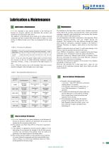
Lubrication & Maintenance Table 4. Viscosity of Lubrication Notes for Lubricant Oil Replacement A) Periodic Lubricant replacement l.First time : After 500~1000 hours continuous running (about 2~4 months) 2.Second time: after the first replacement , at every 3000 hours(about 6~12 months) of operation. B) To replace the lubricating oil, please make sure that the lubrication is clean and the oil filling hole is wiped clean to prevent moisture and impurities from entering. C) The temperature rise increases the internal pressure of the mailbox and causes the oil to leak. Regularly clean the oil hole,...
Open the catalog to page 10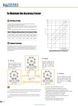
To Maintain the Accuracy Factor■ The Size of Table To install a table on the output shaft, the size of table shall be based on the permitted output torque load for the Torque Te. While high precision is required, the Torque Te shall be 2-3 times larger than the permitted output torque load; therefore, the twist of the output shaft needs to be reduced. The table’s maximum diameter shall be 5 times less than the nominal dimension. Table 6. Maximum Diameter(mm) for the General Tables Hansheng indexer precision is dedicated by angle and guaranteed to be ±30” for general grade and ±15” for precision...
Open the catalog to page 11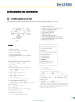
■ Ex.(1) When applying the sub-table Select a suitable size and model of index unit and necessary power of drive motor in following data shown as Fig-1 are given. 1. Number of index stop : S=6 2. Time ratio in move : Dwell for one rotation of cam 3. Revolution of input shaft : N=80rpm 4. Cam curve : Modified Sine curve 8. Rotary table is held with its bottom sliding surface to 9. support loaded weight.(effective radius R=100mm) Solution 1-1 Numbers of index stop: S=6 1-2 Time Ratio in rotation /dwell 1:2, there for index angle 1-3 Revolution of input shaft: N=80rpm 1-4 Cam Curve as Modified ,...
Open the catalog to page 12All Hansheng Automation (Dongguan) Co., Ltd. catalogs and technical brochures
 Hypoid gear reducer HRH-160
32 Pages
 Large rotary table HRTK series
32 Pages
 Cam index unit
96 Pages
 Intermittent indexer
96 Pages
 Intermittent indexer DF series
96 Pages
 Right-angle indexer 450DT
96 Pages
 Rotary indexer
96 Pages
 Oscillating indexer
96 Pages
 Rotary indexer 180DF series
96 Pages
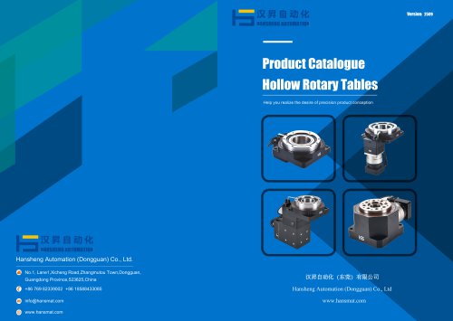
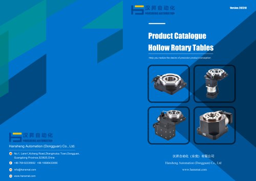 Hollow rotary table
32 Pages
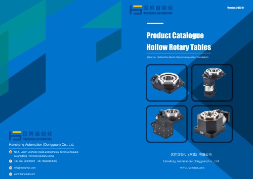 Rotary positioning table
32 Pages
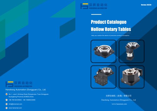 Electric actuator
32 Pages
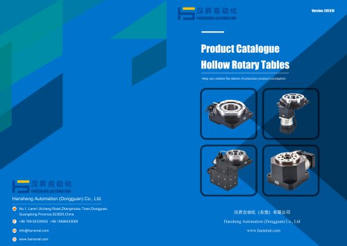 Rotary actuator HRT Series
32 Pages
 Plastic machining
36 Pages
 Copper machining
36 Pages
 Metal machining
36 Pages
 Harmonic gear reducer SHF-IV
8 Pages
 Harmonic gearhead SHF-17-I
8 Pages
 Worm gear reducer SHF-32-I
8 Pages
 Strain wave gearbox
4 Pages
 Actuator gear reducer SHD-03
4 Pages
 Harmonic gear reducer SHD-08
4 Pages
 Strain wave gearhead SHD-11
4 Pages
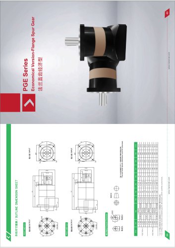
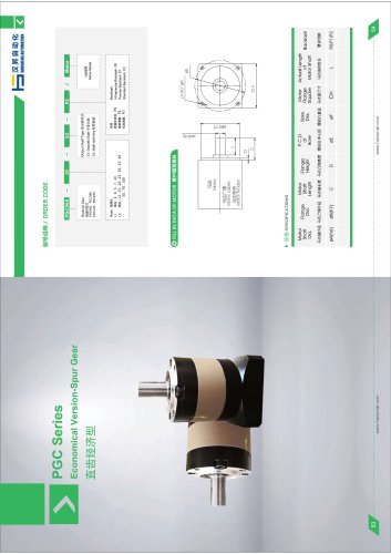
 Planetary gearbox PGE series
4 Pages
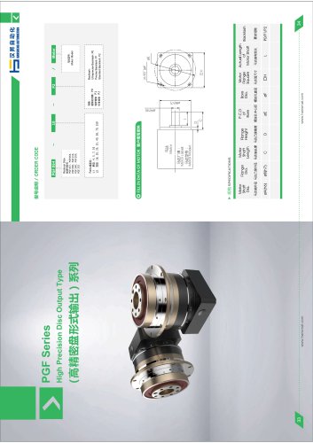
 Spur gearbox PGF047 series
5 Pages
 Planetary gearbox PGF064
5 Pages
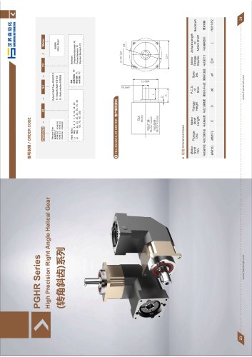
 Planetary gearbox PGHR115
5 Pages
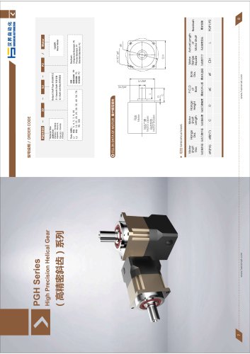
 Planetary gearbox PGH142
5 Pages
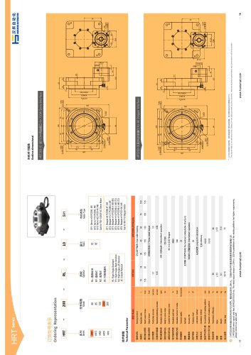 Rotary actuator HRT200-10
2 Pages
 CSD Series Harmonic Drive
3 Pages
 Rotary indexer PU320
2 Pages
 Rotary indexer PU250DS
2 Pages
 Rotary indexer PU225DS
2 Pages
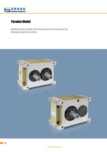 Rotary indexer PU175DS
2 Pages
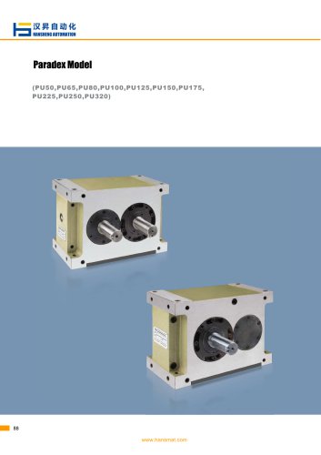 Rotary indexer PU150DS
2 Pages
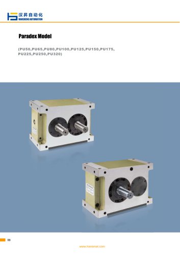 Intermittent indexer PU125DS
2 Pages
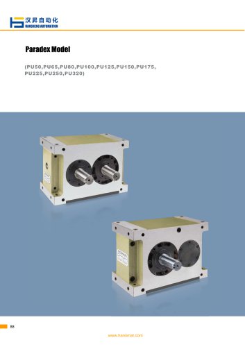 Rotary indexer PU100DS
2 Pages
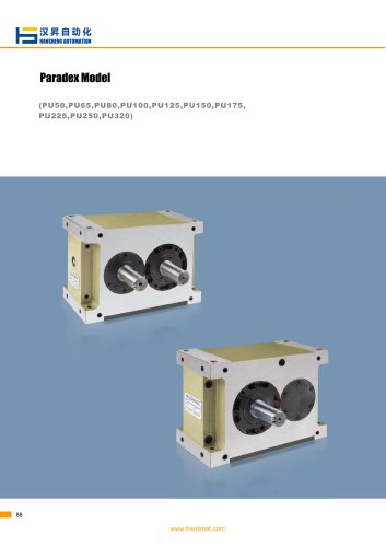 Rotary indexer PU80DS
2 Pages
 Oscillating indexer PU65DA
2 Pages
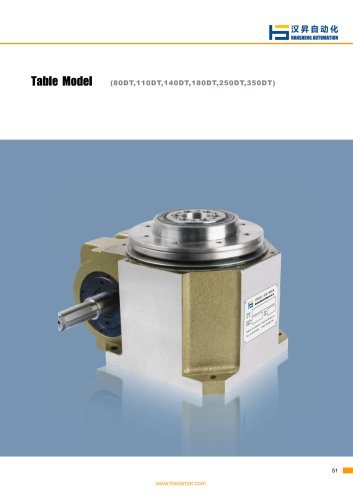 Rotary indexer 350DT
2 Pages
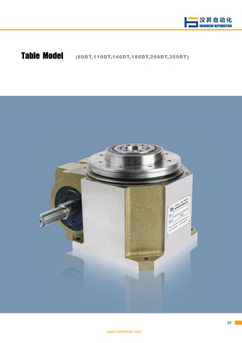 Rotary indexer 250DT
2 Pages
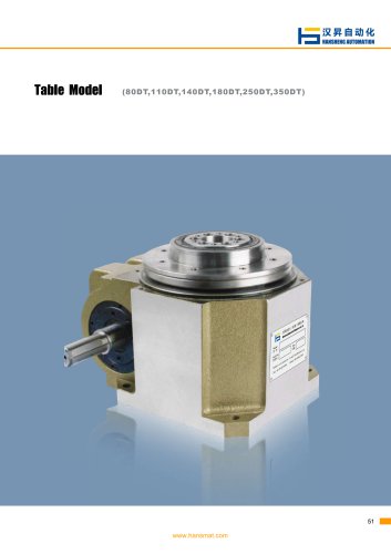 Rotary indexer 210DT
2 Pages
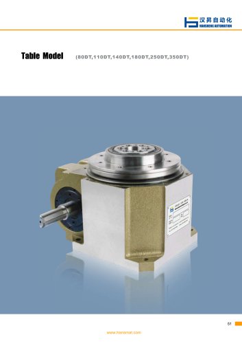 Rotary indexer 180 DT
2 Pages
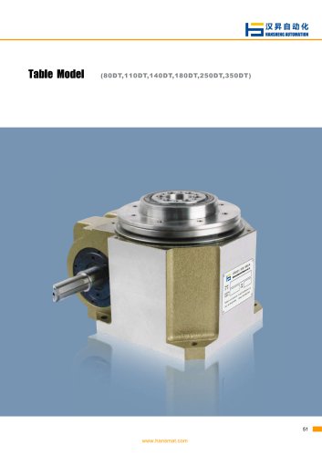 Rotary indexer 110DT
2 Pages
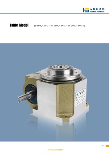 Intermittent indexer 80DT
2 Pages
 Table model 50DT series
2 Pages
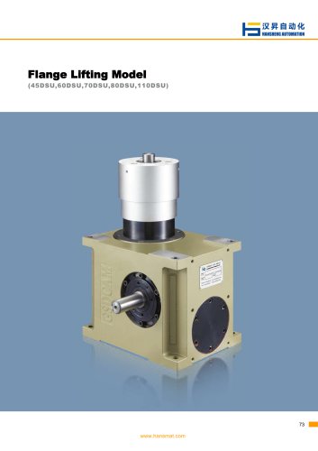 110DSU indexer
2 Pages
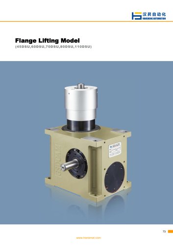 customize 80DSU series
2 Pages
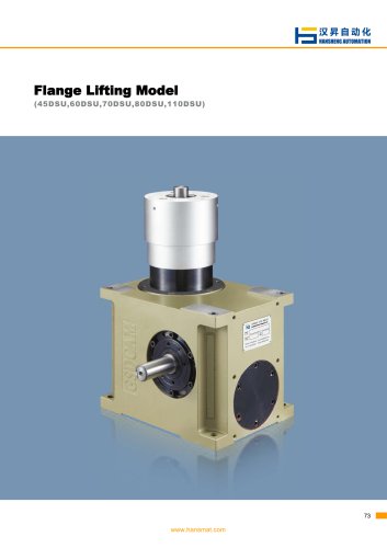 70DSU Indexing Turntable
2 Pages
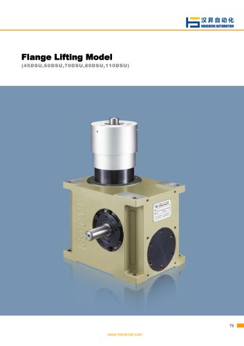 60DSU cam indexer
2 Pages
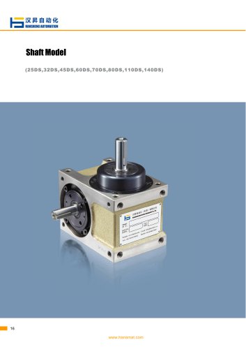 140DS series Cam Index Drive
2 Pages
 110DS Cam Driven Indexer
2 Pages
 Intermittent indexer 80DS
2 Pages
 Rotary indexer 70DS
2 Pages
 DS series 60DS indexer
2 Pages
 Cam indexer 45DS
2 Pages
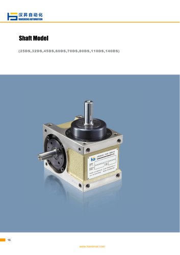 Shaft model series 32DS
2 Pages
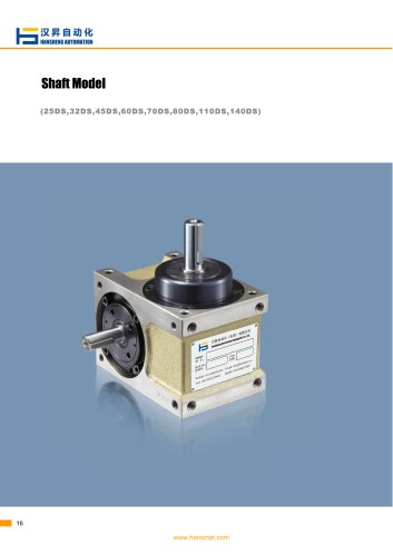 Shaft model 25DS series
2 Pages
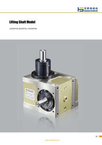 100DFN Rotary Cam Indexers
2 Pages
 80DFN series cam indexer
2 Pages
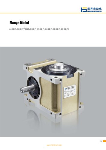 Rotary indexer 180DF
2 Pages
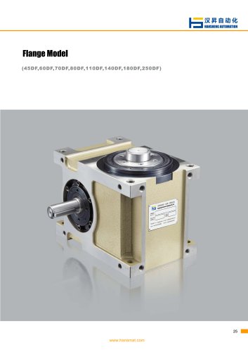 Rotary indexer 140DF
2 Pages
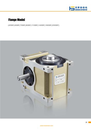 Rotary indexer 110DF
2 Pages
 Intermittent indexer 80DF
2 Pages
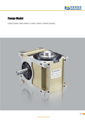 Rotary indexer 70DF
2 Pages
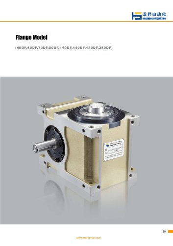 Cam indexer 60DF
2 Pages
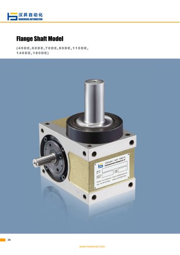 Rotary indexer 180DE
2 Pages
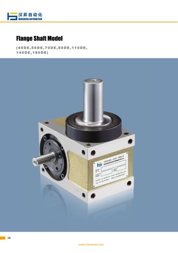 Rotary indexer 140DE
2 Pages
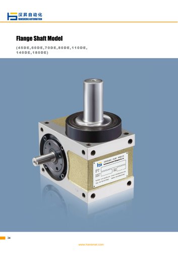 Rotary indexer 110DE
2 Pages
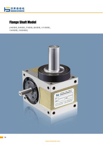 Rotary indexer 80DE
2 Pages
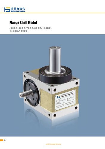 Cam indexer 70DE
2 Pages
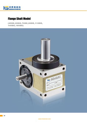 Rotary indexer 60DE
2 Pages
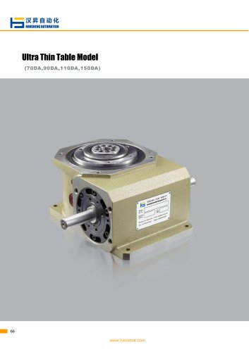 Rotary indexer 150DA
2 Pages
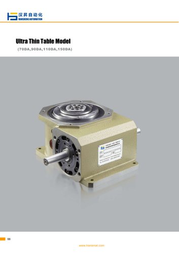 Intermittent indexer 110DA
2 Pages
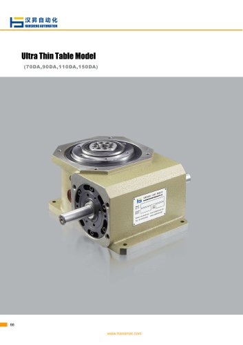 Intermittent indexer 90DA
2 Pages
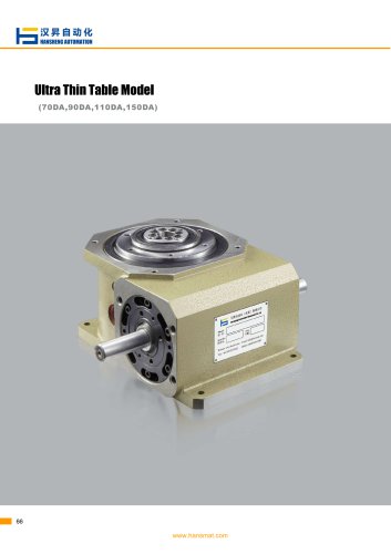 Intermittent indexer 70DA
2 Pages
 Product Catalogue
12 Pages
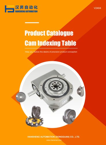 Product Catalogue Cam Indexing Table
105 Pages


























- Actuator
- Planetary gearbox
- Electric actuator
- Coaxial gearhead
- Positioning table
- Power transmission belt
- Conveying belt
- Precision gearhead
- Right angle gearhead
- Compact gearhead
- Solid-shaft gearhead
- Hollow-shaft gearhead
- Gear train gear reducer
- Motorized positioning table
- Gearbox for industrial applications
- Industrial strip
- Machining service
- Transmission gearhead
- Compact actuator