- Catalogs
- HANGZHOU SINO-DEUTSCHE POWER TRANSMISSION EQUIPMENT CO., LTD.
- FF Parallel Shaft Reducer
FF Parallel Shaft Reducer
1 /63Pages

FF Parallel Shaft Reducer
1 /63Pages
Catalog excerpts

since 1976 □ fixed star FF SERIES PARALLEL SHAFT GEAR REDUCERS/GEARED MOTORS FK SERIES HELICAL BEVEL GEAR REDUCERS/GEARED MOTORS FS SERIES HELICAL WORM GEAR REDUCERS/GEARED MOTORS
Open the catalog to page 1
Originally |established as Hangzhou Reducer Factory in 1976, Fixedstar Group hasTm3ergon^lgnmcant transformation and growth. Recognized as the foremost manufacturer and exporter of worm gear reducers in China since 1993, we were granted the first export license for reducers, marking a significant milestone for our organization. Today, our commitment extends beyond mere manufacturing; we are deeply involved in comprehensive research and strategic trading. Power transmission products remain at the core of our business operations, receiving our utmost attention and expertise. With a substantial...
Open the catalog to page 2
With I EC Motor Flange ^PI 17-P118 Mounting Positions and Plugs Other Products from Fixedstar
Open the catalog to page 3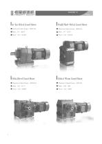
FIKGOSTFn "? EDUCED I In-line Helical Geared Motor ■ Maximum Output Torque: 18000 Nm I Parallel Shaft-Helical Geared Motor I Maximum Output Torque: 18000 Nm I Helical Bevel Geared Motor ■ Maximum Output Torque: 50000 Nm ■ Maximum Output Torque: 4200 Nm
Open the catalog to page 4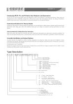
Introducing FR,FF, FK, and FS Series Gear Reducers and Gearmotors Our FR, FF, FK, and FS series gear motors are designed to meet a vast spectrum of industrial requirements. These series are distinguished by their remarkable compactness, minimal noise output, high load-bearing capacity, low energy consumption, superior torque transmission, optimal efficiency, minimal temperature rise, and extended lifespan. Customized Solutions for Diverse Needs Embracing a philosophy of modular design and optimization, we are dedicated to fulfilling diverse customer needs across various applications. Multi-stage...
Open the catalog to page 5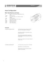
Input ConfigurationMotor Specifications and Codes D.. Gearbox Connecting with Integral Motors Only ../BMG Disc Brake Motor ../HF Disc Brake Motor with Manual brake ../TF Motor with Thermistor (PTC resistor) ../EXP Explosion proof Motor ../SRD Roller tables' Motor ../RS Motor with Backstop D132S4/VEF/BMG/HF/RS 132 Frame Size Converter Motor with Disc Brake and Hand Release and Backstop Frame Size and Motor Power please refer to Page P42 and P45 Please Specify Output Shaft (A Side) Clockwise or Anti-Clock-wise when Back Stop Need on the motor. Please refer to Page PI 4 for A Side or B Side of the...
Open the catalog to page 6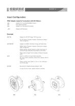
FIKGOSTfn ^EDUCED With Adapter ready for Connection with IEC Motors AM.. Adapter for mounting IEC/NEMA motors AD.. Input Shaft Assembly AQ.. Adapter for mounting Servomotors ../RS Adapter with Backstop AM 132 Adapter for IEC B5 Flange 132 Frame size IEC B5 Motor Flange's Adapter Dimensions please refer to Page P47 AM 182/RS Adapter for NEMA 182 Motor Flange with Back Stop NEMA Motor Flange's Adapter Dimensions please refer to Page P49 Please Specify Output Shaft (A Side) Clock-wise or Anti-Clock-wise when Back Stop Need on the motor. Please refer to Page PI 4 for A Side or B Side of the gear...
Open the catalog to page 7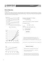
FIKEOSTFR DEDUCE'} Drive Selection Service Factor For the FR, FF, and FK series, the service factor is determined based on both daily operating time and the starting frequency Z. Three load classifications are considered, each dependent on the mass acceleration factor. For the FS series of helical-worm gear units, two additional service factors need to be considered, alongside the service factor jjj from Figure 1. These are (service factor from ambient temperature) and fB2(service factor from cyclic duration factor). For FRs FFv FK series, select fB from Figure 1. For helical-worm gear units:...
Open the catalog to page 8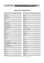
Application Classification In case of service factor for applications more than class III, please contact Fixedstar technician for more information.
Open the catalog to page 9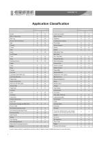
Application Classification In case of service factor for applications more than class III, please contact Fixedstar technician for more information.
Open the catalog to page 10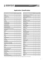
Application Classification In case of service factor for applications more than class III, please contact Fixedstar technician for more information.
Open the catalog to page 11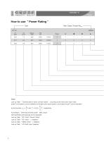
How to use " Power Rating " Type Max. Output Torque Mamax Look up Table “ Technical data for direct connect motors ” , according to the motor type, motor rated power Peand speed no can be obtained, so the gear units output speed na and output torque T can be calculated According to “Overhung and Axial Loads” table, shaft permitted overhung load can be calculated. Look up Table “ EC Direct Connect Motor" Look up Table “ EC Motor ’ s Adapters” Look up Table “ NEMA Motor' s Adapters ” Look up Table “AD Shaft Input Adap
Open the catalog to page 12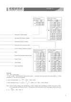
Alternative AD Shaft Adapter Alternative NEMA Motors' Adapter NEMA Motors' Adapter Alternative IEC Motors' Adapter Alternative Direct Connection Motor Gear Unit stage (2-stages or 3-stages) Ratio Output Shaft Permitted Overhung Load Output Torque Output Speed Motor Rated Power K Look up Table “ Technical data for direct connect motors ” , according to the motor type, motor rated power P^* = 2.2 kW and speed no = 1445 rpm can be obtained. 2, Gear Unit Output Speed: i\=■^L = 1445 4- 17.82 = 81.09 3x Gear Unit Output Torque: T = 9550 X-= 9550 x 2.2 x 0.96 -f- 81.09 = 249 Nm Note: For FR, FF series,...
Open the catalog to page 13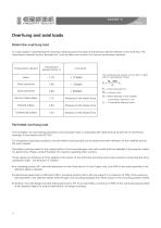
Overhung and axial loadsDetermine overhung load A crucial aspect in ascertaining the resulting overhung load is the type of transmission element affixed to the shaft end. The transmission element factors, denoted as f, must be taken into account for various transmission elements The overhung load exerted on the motor or gear shaft is calculated as follows : Fr = Overhung load in N Md = Torque in Nm d0 = Mean diameter of the installed transmission element in mm fz = Transmission element factor The foundation for ascertaining permitted overhung loads relies on calculating the rated bearing service...
Open the catalog to page 14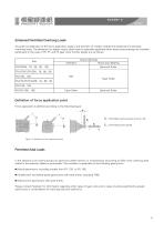
Accurate consideration of the force application angle a and direction of rotation enables the attainment of elevated overhung loads. The allowance for higher output shaft loads is especially applicable when heavy-duty bearings are installed, particularly in the case of FR, FF, and FK gear units. Further details are as follows: Permitted Axial Loads In the absence of an overhung load, an axial force (either tension or compression) amounting to 50% of the overhung load stated in the selection tables is permissible. This condition is applicable to the following gearmotors: • Helical gearmotors,...
Open the catalog to page 15All HANGZHOU SINO-DEUTSCHE POWER TRANSMISSION EQUIPMENT CO., LTD. catalogs and technical brochures
 FS Helical Worm Reducer
64 Pages
 Shaft Mounted Reducer
24 Pages
 FIXGDSTRR REDUCER
32 Pages
 FV&FW Series Reducer
24 Pages
- Electric gearmotor
- Coaxial gearhead
- Precision gearhead
- Direct current gear-motor
- Right angle gearhead
- Compact gearhead
- Solid-shaft gearhead
- Flexible coupling
- Gear train gear reducer
- Gearbox for industrial applications
- Transmission gearhead
- Single-stage gearhead
- Coaxial gearmotor
- Compact gear-motor
- Helical gear gearhead
- Gear train gearmotor
- Machines gearbox
- Dual-stage gearbox
- High-performance gearhead