- Catalogs
- Hangzhou IECHO Science & Technology Company
- CutterServer User Manual
CutterServer User Manual
1 /42Pages

CutterServer User Manual
1 /42Pages
Catalog excerpts

CutterServer User Manual CutterServer User Manual Hangzhou IECHO Science & Technology Co., Ltd.
Open the catalog to page 1
CutterServer User Manual
Open the catalog to page 2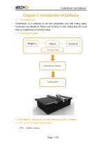
CutterServer User Manual Chapter 1: Introduction of Software 1.1 Introduction CutterServer is a software to set tool parameters and edit cutting tasks. Customers use iBrightcut, iPlycut and Smartcut to edit cutting files and send them to CutterServer to control cutting. Produce task CutterServer Editing Cutting task 1.3 Software Installation and Operating Environment 1.3.1 PC and DSP board requirement CPU:2.0GHz or above
Open the catalog to page 4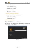
CutterServer User Manual Memory:4GB or above Graphics card:256MB or above Resolution:1024×720 or above DSP Version:2.2.8 or above FPGA Version:1.3.7 or above 1.3.2 System and Software requirement System:Windows 7、Windows 10(32bit\64bit) CutterServer Version:V 3.0.0.1 CutterServer Date:2018.8.30.1 1.3.3 Software Installation Note: WIN7, WIN10 need to run as administrator Note: Please select Chinese or English installation package according to the system's language. As shown in Figure 1.
Open the catalog to page 5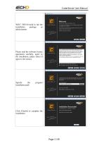
CutterServer User Manual WIN7, WIN10 need to run the installation package as administrator Please read the software license agreement carefully, agree to the installation, please select [I agree to the terms] Specify the installation path Click [Finish] to complete the installation
Open the catalog to page 6
CutterServer User Manual 1.4 Software interface and function introduction 1.4.1 Configuration instruction Before using the software, check whether the cutting equipment is a special model. If it is a dual-beam equipment, a multi-inverter equipment or a 1KW router equipment, please modify the parameters in the SysConfig configuration file in the program directory. The parameter modification method is as follows: 1 Dual-beam: Modify the parameters in the SysConfig configuration file in the program directory, change the feeding mode to pull mode Push=1. 2 Multi-inverter or 1KW router equipment:...
Open the catalog to page 7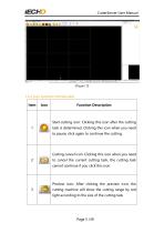
CutterServer User Manual (Figure 3) 1.4.3 Icon function introduction Item Function Description Start cutting icon: Clicking this icon after the cutting 1 task is determined. Clicking this icon when you need to pause; click again to continue the cutting. Cutting cancel icon: Clicking this icon when you need 2 to cancel the current cutting task, the cutting task cannot continue if you click this icon Preview icon: After clicking the preview icon, the 3 cutting machine will show the cutting range by red light according to the size of the cutting task
Open the catalog to page 8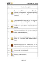
CutterServer User Manual Function Description Conveyor icon: Click the conveyor icon. The cutting 4 machine will automatically feed material according to the set feeding length (only for the machine with conveyor). Vacuum pump switch icon: Click this icon to turn on the vacuum pump, and click again to turn it off. Pump reverse blowing icon: control pump reverse blowing Machine zero point icon: Click this icon to return the cutting head to the zero point Z-axis reset icon: select tool and click this icon, the 8 system will automatically reset the selected tool in Z-axis. Relative origin point...
Open the catalog to page 9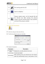
CutterServer User Manual film covering switch for GLS Pressure cylinder switch, can be manually fed with 14 the direction key (after pressing the pressure cylinder, move the machine head in the X direction, and then lift the pressure cylinder) 1.4.4 Auto Knife Initialization Select the cutting tool, then click AKI icon The following dialog box pops up, click [AKI] Parameter Description: Parameter Pre-aligned tool Display the currently selected tool name holder Current height start testing Current tool depth After checking, press any direction key, the machine head will automatically move to the...
Open the catalog to page 10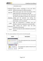
CutterServer User Manual initialization point. initialization Actual position coordinates of the AKI device point XY Spare felt (different parameters for different position) When using router tool, check the thickness of the spare felt and fill in the thickness of the felt. Compensate the error between the AKI device and the table. By the difference between the manual tool knife down setting and the automatic tool setting, the compensation compensation range is ±5mm (the first, second and third holders can be inconsistent). After the compensation is modified, must click Modify to make the compensation...
Open the catalog to page 11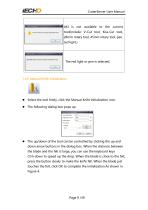
CutterServer User Manual AKI is not available to the current tool(include: V-Cut tool, Kiss-Cut tool, 28mm rotary tool, 45mm rotary tool, pen, red light.) 1.4.5 Manual Knife Initialization Select the tool firstly, click the Manual Knife Initialization icon. The following dialog box pops up The up/down of the tool can be controlled by clicking the up and down arrow buttons in the dialog box. When the distance between the blade and the felt is large, you can use the keyboard keys Ctrl+down to speed up the drop. When the blade is close to the felt, press the button slowly to make the knife fall....
Open the catalog to page 12
CutterServer User Manual Maximum falling depth limit By manual knife initialization, the maximum falling depth is 260mm. Resetting the model will clear the maximum depth for all the tools, all set to 10mm. Auto Knife Initialization depth or Manual Knife Initialization depth plus 1mm is the maximum depth. When manually modify the depth of the tool, can not exceed the maximum depth of the tool, but can be less than the maximum depth of the tool. If need to change the maximum range, please perform the initialization again. 1.4.6 Tools Parameters Select the tool to be set, right-click to...
Open the catalog to page 13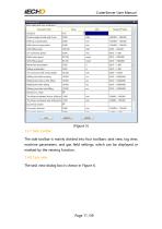
CutterServer User Manual (Figure 5) 1.4.7 Side toolbar The side toolbar is mainly divided into four toolbars: task view, log view, machine parameters, and gas field settings, which can be displayed or masked by the viewing function. 1.4.8 Task view The task view dialog box is shown in Figure 6.
Open the catalog to page 14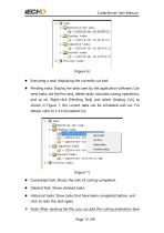
CutterServer User Manual Executing a task: displaying the currently cut task Pending tasks: Display the tasks sent by the application software. Can send tasks, set the first task, delete tasks, simulate cutting operations, and so on. Right-click [Pending Task] and select [Analog Cut], as shown in Figure 7, the current data can be simulated and cut. For details, refer to 2.3.4 Simulated Cut. Completed task: Shows the task of cutting completed. Deleted Task: Shows deleted tasks. Historical tasks: Show tasks that have been completed before, and click to redo the task again. Note: After sending...
Open the catalog to page 15All Hangzhou IECHO Science & Technology Company catalogs and technical brochures
 iBrightCut Manual
78 Pages
 IPlyCut User Manual
30 Pages
 IMulCut V1 User Manual
27 Pages
 ISO
ISO1 Page
 CE
CE1 Page
 Textile and apparel industry
2 Pages
 TECHNICAL CONSTRUCTION FILE (TCF)
190 Pages
 LCKS
LCKS4 Pages
 PK1209 PRO & PK1209 PRO MAX
2 Pages


- Metal cut-off machine
- Automatic cut-off machine
- Cutting machine for industrial applications
- Knife cutting system
- High-precision cutting center
- Sheet metal cutting machine
- High-speed cut-off machine
- Plastic cutting machine
- Precision cut-off machine
- Aluminum cutting center
- Fabric cutting machine
- Cutting machine for the automotive industry
- Sheet cutting machine
- High-performance cutting machine
- CE cutting machine
- Compact cut-off machine
- High-efficiency cutting machine
- Three-phase cut-off machine
- Cutting system with automated loading