
Catalog excerpts
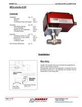
MCx-xxxAx-8.09 Contents Installation pg. 1-3 Mounting pg 1 Wiring pg 2 Connecting Power and Signal pg 2-3 Operation pg. 4-6 DIP Switch settings Torque Settings Signal loss and Calibration Troubleshooting Appendix pg. 7-9 Changing number of turns Speed and Torque Details Dimensions Installing a cable Part Number Breakdown Installation Mounting: Usually, the actuator has to be mounted and supported as shown in the picture to the left. Exceptionally, and only if the application is vibration free and the tubing is minimum ¼” dia. stainless, the actuator may be suspended on the tubing itself. User’s mounting surface Cable Entry Valve fluid connections Mounting Bracket
Open the catalog to page 1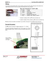
Wiring: The actuator comes standard with a Turck 5 position connector and a 20’ cable with plug. Cut the cable to the length required and then connect according to the following wire color schematic: Colour White -> Black -> Grey -> Brown-> Blue -> Function +24VDC Power Gnd. Output Signal (4..20mA)* Not connected Isolated** Input Signal Gnd. Isolated** Input + Signal (4..20mA) * “feedback” available in MCx-xxxAF version of actuator only. ** “isolated” available in MCx-xxxAI and xxxAF versions of actuator only. Otherwise, if the Turck cable is not included in your actuator, see pg.9 for more...
Open the catalog to page 2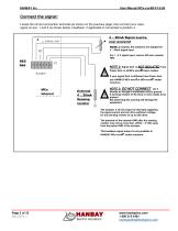
Connect the signal: Locate the correct connection terminals as shown on the previous page, then connect your input signal on pos. 1 and 2 as shown below. Feedback, if applicable is connected to position 4. 4 .. 20mA Signal source, user powered NOTE 1: Usually, the actuators are shipped for 4 .. 20mA signal input. For 1 ..5 V signal input, remove 250 ohm resistor R66. P1 NOTE 2: Signal Gnd. is NOT ISOLATED from Power Gnd. in all MCx-xxxAB basic models. Actuator If your signal Gnd. is different from Power Gnd. use HANBAY MCx-xxxAI or MCx-xxxAF model actuators. External 4 .. 20mA Sensing...
Open the catalog to page 3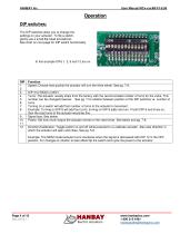
Operation DIP switches: The DIP switches allow you to change the settings on your actuator. To flip a switch, gently use a small flat-head screwdriver. See chart on next page for DIP switch functionality. In this example DIPs 1, 2, 6 and 12 are on. Function Speed: Choose how quickly the actuator will turn the drive wheel. See pg. 7-8. DIP 3 for MCM or MCH Turns: The actuator usually ships from the factory with the recommended number of turns for the valve. This number can be changed however. See pg. 7 for relation between position of the DIP switches vs. number of turns. Turning on a switch...
Open the catalog to page 4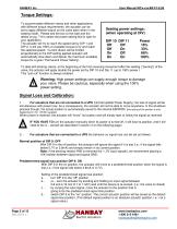
Torque Settings: To accommodate different valves and other applications with different torque requirements, the actuator can be set to apply different torque on the valve stem when in the seating mode. Please see the box to the right and the tables on pg. 7-8 to select the power setting that is right for your application. The actuator will try to reach the speed set by DIP 1 and DIP 2. It will use 100% of available torque to try and reach the selected speed. Current drawn will be limited proportionally to the DIP setting applied actuator will automatically slow down and deliver the maximum...
Open the catalog to page 5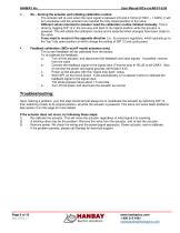
Re – Zeroing the actuator and initiating calibration routine: The actuator will re-zero when the input signal is between 2.8 and 4.16mA (0.700V – 1.040V). It will turn clockwise until the actuator has reached the fully closed position of the valve. Different valves mounted to actuator need the calibration routine initiated manually. This is done by toggling DIP 12 in the one way and back to its original position while the actuator is powered. This will initiate the calibration routine and is essential when changes have been made to the valve. If you need to re-zero in the opposite direction...
Open the catalog to page 6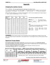
Appendix Changing the number of turns: The 4 .. 20mA (or 1.. 5V) input signal represents a total span of a number of turns. i.e.: If you set the number of turns to 2, then a signal of 12mA will set the actuator to exactly 1 turn from the fully closed position. 15 mA will give: (15-4)/16=0.6875 => 68.75% of 2 turns => 1.375 turns from closed etc. With the DIP switch settings, you can adjust anything between 1 and 31 turns to represent the full signal range of 4 .. 20mA. Check in the table below. (1 = “On” 0 = “Off”) For more turns set DIP 4 as follows: DIP 4=0 This will add 16 turns to the...
Open the catalog to page 7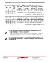
Speed and Torque of MCM-xxxAx Actuators DIP 1 NOTE: If actuator is MCK-xxxAx, divide torque values by 3. Operating torque is 100%. These torque values are for valve seating. To convert in-lbs to Nm, divide the in-lbs value by 9 Speed and Torque of MCH-xxxAx Actuators Time for Torque in in-lbs Torque in in-lbs Torque in in-lbs Torque in in-lbs 1 turn DIP 1 DIP 2 (sec) 16% Power* 33% Power* 66% Power* 100% Power* 12VDC 24VDC 12VDC 24VDC 12VDC 24VDC 12VDC 24VDC OFF OFF 90 44 88 88 177 166 332 450 900 OFF ON 45 Operating torque is 100%. These torque values are for valve seating. ON OFF 30 ON ON...
Open the catalog to page 8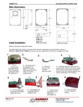
Main Dimensions: MCL-xxxAx MCM-xxxAx MCJ-xxxAx Cable Installation: MCK-xxxAx models MCH-xxxAx models Select a connection cable with 5 leads. The liquid tight strain relief on the base of the actuator is designed to accommodate a cable of O.D. 2.5 - 6.5mm (0.10 - 0.26in). Be sure to not use a cable with an OD that is no bigger than this! 1.- Remove the liquid tight fitting from the actuator casing and insert the cable into it. 2.- The cable has to be stripped of its jacket for 2 inches (50mm) and the wires need 1/8” (3mm) stripped ends. 5.- Put the liquid tight fitting back and tighten...
Open the catalog to page 9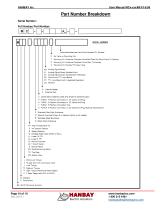
Part Number Breakdown Serial Number: Full Hanbay Part Number:
Open the catalog to page 10All Hanbay Inc. catalogs and technical brochures
-
Rxx-Series Spec Sheet
2 Pages
-
Mxx Series Spec Sheet
2 Pages
-
User Manual MCx-xxxAS Modbus
15 Pages
-
Rxx-Series Part Number Guide
1 Pages
-
Mxx Series Part Number Guide
1 Pages
-
User Manual RDx-xxxDT TTL
8 Pages
-
User Manual RCx-xxxAx 4..20mA
10 Pages
-
User Manual MDx-xxxDT TTL
8 Pages


