
Catalog excerpts
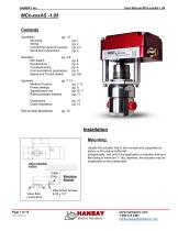
MCx-xxxAS -1.05 Contents Installation pg. 1-3 Mounting Wiring Connecting signal and power Serial port connections Operation pg. 4-6 DIP Switch Recalibration Troubleshooting Communications parameters Speed and Torque details Appendix pg. 7-14 Modbus Protocol pg. 7-12 Power settings pg. 8 Signal/power loss pg 10-11 Setting actuator address pg. 13 Dimensions Cable Installation Part Number Breakdown Installation Mounting: Usually the actuator has to be mounted and supported as shown in the picture to the left. Exceptionally, and only if the application is vibration free and the tubing is minimum ¼” dia. stainless, the actuator may be suspended on the tubing itself. User’s mounting surface Cable Entry Valve fluid connections Mounting Bracket
Open the catalog to page 1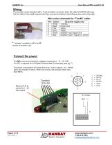
Wiring: The actuator comes standard with a Turck 6 position connector and a 20’ cable 22 AWG/6 with plug. Cut the cable to the length required and then connect according to the following wire color schematic: Colour White Black Pink Grey Brown Blue DC power supply only +24VDC Power Gnd TD(A) TD(B) Isolated* Input Signal Gnd Isolated* Input + Signal (4...20mA) “isolated” available in MCx-xxxSI version of actuator only Connect the power: The MCx may be connected to voltages ranging from: 12 – 24 VDC. 18 VDC is required for full ‘Digital Potentiometer’ functionality (see pg. 7) The power...
Open the catalog to page 2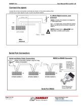
Connect the signal: Locate the correct connection terminals as shown in the picture above then connect your input signal on pos. 3 and 4 as shown below. 4…20mA Signal source, user powered NOTE 1: Usually, the actuators are shipped for 4...20mA signal input. For 1…5 V signal input, remove 250 ohm resistor R66 (or cut just one wire as shown in picture on page 2) NOTE 2: Signal Gnd is ISOLATED from Power Gnd. in all MCx-xxxSI models. Serial Port Connection:
Open the catalog to page 3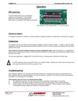
Operation DIP switches: The DIP switches allow you to change the settings on your actuator. To flip a switch, gently use a small flat-head screwdriver. See chart on next page for DIP switch functionality. DIP switches. In this example DIPs 1, 2, 6 and 12 are on. Direction of rotation: To change the direction of rotation, turn off the actuator, change the position of switch DIP 12 and power it up again. Calibration: The actuator will re-zero when the input signal is between 2.8 and 4.16mA (0.700V – 1.040V). It will turn either clockwise or anti-clockwise (depending on direction selection of...
Open the catalog to page 4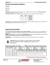
Set the communication parameters: Data bits: 8 Parity: None Stop bits: 1 Baud Rate: The communication baud rate can be set by using the first two positions of the DIP switch selector. Check in the table below. (1 = “On” 0 = “Off”). To change the baud rate, turn off the actuator, change the setting of DIP switches and power it up again. DIP 1 0 0 1 1 Response time: The response time is between 8ms to 35ms, this means, after sending a frame, you have to wait at least 35ms for the answer coming back from the actuator Speed and Torque Details: To set the maximum speed change the value of...
Open the catalog to page 5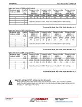
Speed and Torque of MCM-xxxAS Actuators Maximum Speed Address 0x0000 Operating torque is 100% These torque values are for valve seating. To convert in-lbs to Nm, divide the in-lbs value by 9 Speed and Torque of MCH-xxxAS Actuators Maximum Speed Address 0x0000 Operating torque is 100% These torque values are for valve seating. To convert in-lbs to Nm, divide the in-lbs value by 9 Speed and Torque of MCF-xxxAS Actuators Maximum Speed Address 0x0000 Operating torque is 100% These torque values are for valve seating. To convert in-lbs to Nm, divide the in-lbs value by 9 Note: 66% setting and...
Open the catalog to page 6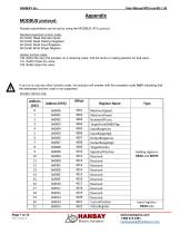
Appendix MODBUS protocol: Actuator parameters can be set by using the MODBUS (RTU) protocol. Standard supported function codes: 02 (0x02) Read Discrete Inputs 03 (0x03) Read Holding Registers. 04 (0x04) Read Input Registers. 06 (0x06) Write Single Register. Hanbay function codes: 100 (0x64) Re-zero the actuator on a metering valve, find the home or resting position for ball valve. 101 (0x65) Close the valve. 102 (0x66) Open the valve. If you try to use any other function code, the actuator will answer with the exception code 0x01 indicating that the attempted function code is not supported....
Open the catalog to page 7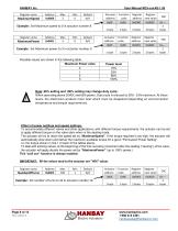
HANBAY Inc Register name User Manual MCx-xxxAS-1.05 Address 0x0000 Register Register address new value 0x0000 0x0000 Example: Set Maximum speed to 0 in actuator number 8 Register name Example: Set Maximum power to 3 in actuator number 9 Possible values are shown in the following table. Note: 66% setting and 100% setting may change duty cycle: When operating above 20VDC and 66% power, Duty cycle is reduced to 50% - 25% maximum. At these levels, the electronics produce more heat which must be dissipated (depending on environmental temperature and torque requirements). Effect of power settings...
Open the catalog to page 8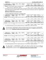
HANBAY Inc Register name User Manual MCx-xxxAS-1.05 Address 0x0003 Example: To have actuator number 11 taking the target position from the “TargetPosition” register Register CRC new value 0x0000 0x---2 2 bytes bytes This flag tells the actuator where the target position is coming from. If this value is 1 the actuator will take the value from 4..20mA input as its target position. If this value is 0 the actuator will take the value from “TargetPosition” register as its target position. (Remember: all values sent to actuator are HEX) ** Factory configuration of valve type, e.g. metering or...
Open the catalog to page 9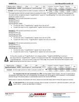
HANBAY Inc Register name User Manual MCx-xxxAS-1.05 Address TargetPosition 0x0008 InputRangeLow InputRangeHigh Example: Set the target position to 3000 in actuator number 18 Actuator Function Register address code address 0x12 0x06 0x0008 1 byte 1 byte 2 bytes Register new value 0x0BB8 2 bytes The target position tells the actuator where to position the valve. If “TargetPosition” equals to “InputRangeLow” the valve will be completely closed, if TargetPosition” equals to “InputRangeHigh” the valve will be opened t o the maximum number of turns. Example 1: If the actuator parameters are set...
Open the catalog to page 10All Hanbay Inc. catalogs and technical brochures
-
Rxx-Series Spec Sheet
2 Pages
-
Mxx Series Spec Sheet
2 Pages
-
Rxx-Series Part Number Guide
1 Pages
-
Mxx Series Part Number Guide
1 Pages
-
User Manual RDx-xxxDT TTL
8 Pages
-
User Manual RCx-xxxAx 4..20mA
10 Pages
-
User Manual MDx-xxxDT TTL
8 Pages
-
User Manual MCx-xxxAx 4..20mA
10 Pages


