PHOTOMULTIPLIER TUBES AND ASSEMBLIES FOR SCINTILLATION COUNTING&HIGH ENERGY PHYSICS
1 /76Pages

PHOTOMULTIPLIER TUBES AND ASSEMBLIES FOR SCINTILLATION COUNTING&HIGH ENERGY PHYSICS
1 /76Pages
Catalog excerpts
PHOTOMULTIPLIER TUBES AND ASSEMBLIES LTIPLIER TUBES FOR SCINTILLATION COUNTING & HIGH ENERGY PHYSICS
Open the catalog to page 1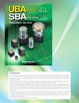
WEB SITE www.hamamatsu.com INTRODUCTION In radiation measurements, scintillation counters which are combinations of scintillators and photomultiplier tubes are used as most common and useful devices in detecting X-, alpha-, beta-, gamma-rays and other high energy charged particles. A scintillator emits flashes of light in response to input radiations and a photomultiplier tube coupled to a scintillator detects these scintillation lights in a precise way. In high energy physics experiments, one of important apparatuses is a Cherenkov counter in which photomultiplier tubes detect Cherenkov radiations...
Open the catalog to page 2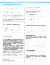
Operating Characteristics This section describes the prime features of photomultiplier tube construction and basic operating characteristics. 1. GENERAL The photomultiplier tube (PMT) is a photosensitive device consisting of an input window, a photocathode, focusing electrodes, an electron multiplier (dynodes) and an anode in a vacuum tube, as shown in Figure 1. When light enters the photocathode, the photocathode emits photoelectrons into vacuum by the external photoelectric effect. These photoelectrons are directed by the potential of focusing electrode towards the electron multiplier where...
Open the catalog to page 4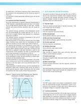
As stated above, the spectral response range is determined by the materials of the photocathode and the window as shown in It is important to select appropriate materials which will suit the 2.5 Luminous and Blue Sensitivity Since the measurement of spectral response characteristics of a PMT requires a sophisticated system and time, it isn't practi- cal to provide spectral response data on each tube. Instead, cathode and anode luminous sensitivity data are usually at- The cathode luminous sensitivity is the photoelectric current from the photocathode per incident light flux (10-5 to 10-2 lu-...
Open the catalog to page 5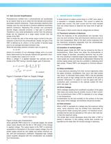
4.2 Gain (Current Amplification) Photoelectrons emitted from a photocathode are accelerated by an electric field so as to strike the first dynode and produce secondary electron emissions. These secondary electrons then impinge upon the next dynode to produce additional secondary electron emissions. Repeating this process over successive dynode stages (cascade process), a high gain is achieved. Therefore a very small photoelectric current from the photoca- thode can be observed as a large output current from the Gain is simply the ratio of the anode output current to the pho- toelectric current...
Open the catalog to page 6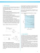
6. TIME RESPONSE In applications where forms of the incident light are pulses, the anode output signal should reproduce a waveform faithful to the incident pulse waveform. This reproducibility depends on the anode pulse time response. These parameters are affected by the dynode structure and applied voltage. In general, PMTs of the linear focused or circular cage structure exhibit better time response than that of the box-and-grid or venetian blind structure. (1) Rise Time (refer to Figure 4) Figure 6 shows typical time response characteristics vs. applied voltage for types R2059 (51 mm dia....
Open the catalog to page 7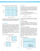
Figure 7: Example of Pulse Linearity Characteristic ANODE PEAK CURRENT (mA) The special voltage distribution ratios are designed to achieve strong electric fields in the later stages of the electron multiplier. Some types are specified with these special voltage dividers. Although the focusing electrodes of a PMT are designed so that electrons emitted from the photocathode or dynodes are collected efficiently by the first or following dynodes, some electrons may deviate from their desired trajectories and col- lection efficiency is degraded. The collection efficiency varies with the position...
Open the catalog to page 8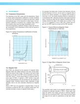
The sensitivity of the PMT varies with the temperature. Figure 10 shows typical temperature coefficients of anode sensitivity around the room temperature for bialkali and high temp, bialkali photocathode types. In the ultraviolet to visible region, the tem- perature coefficient of sensitivity has a negative value, while it has a positive value near the longer wavelength cut-off. Since the temperature coefficient change is large near the lon- ger wavelength cut-off, temperature control may be required in some applications. Figure 10: Typical Temperature Coefficients of Anode Most PMTs are affected...
Open the catalog to page 9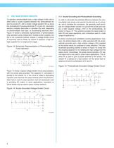
11. VOLTAGE DIVIDER CIRCUITS 11.1 Anode Grounding and Photocathode Grounding To operate a photomultiplier tube, a high voltage of 500 volts to 2000 volts is usually supplied between the photocathode (K) and the anode (P), with a proper voltage gradient set up along the photoelectron focusing electrode (F) or grid (G), secondary electron multiplier electrodes or dynodes (Dy) and, depending on photomultiplier tube type, an accelerating electrode (Acc). Figure 13 shows a schematic representation of photomultiplier tube operation using independent multiple power supplies, but this is not a practical...
Open the catalog to page 10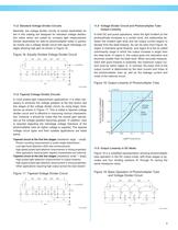
11.2 Standard Voltage Divider Circuits Basically, the voltage divider circuits of socket assemblies lis- ted in this catalog are designed for standard voltage distribu- tion ratios which are suited for constant light measurement. Socket assemblies for side-on photomultiplier tubes in particu- lar mostly use a voltage divider circuit with equal interstage vol- tages allowing high gain as shown in Figure 16. Figure 16: Equally Divided Voltage Divider Circuit 11.3 Tapered Voltage Divider Circuits In most pulsed light measurement applications, it is often nec- essary to enhance the voltage gradient...
Open the catalog to page 11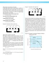
[When light is not incident on the tube] In dark state operation where a high voltage is supplied to a photomultiplier tube without incident light, the current compo- nents flowing through the voltage divider circuit will be similar to those shown in Figure 20 (if we ignore the photomultiplier tube dark current). The relation of current and voltage through each component is given below Interelectrode current of photomultiplier tube Electrode current of photomultiplier tube Voltage divider circuit current Voltage divider circuit voltage Figure 20: Operation without Light Input Figure 21: Operation...
Open the catalog to page 12All HAMAMATSU catalogs and technical brochures
 PHOTON COUTING HEAD
4 Pages
 SPAD MODULES
5 Pages
 LIGHTNINGCURE
29 Pages
 Xenon Flash Lamps
19 Pages
 ORCA-FUSION C14440-20UP
12 Pages
 NanoZommer series
8 Pages
 C13410 series
4 Pages
 C13410-06A
4 Pages
 PMA-12
8 Pages
 L12542
4 Pages
 FLAT EXCIMER
16 Pages
 OPTICAL PINHOLE INSPECTION UNITS
20 Pages
 Optical Gauge series
23 Pages
 L15208-01
3 Pages
 Pulsed Fiber Laser L15187
3 Pages
 L15856-01
3 Pages
 L14001-01
2 Pages
 L11854-336-05
2 Pages
 L14351-02
4 Pages
 LIGHTNINGCURE LC-L1V5
4 Pages
 GC-113A
2 Pages
 Infrared LED L14337-0085R
4 Pages
 Infrared LED L12509 series
9 Pages
 InGaAs camera C12741-11
2 Pages
 InGaAs camera C12741-03
2 Pages
 IMAGEMX2 series
8 Pages
 ORCA-Flash4.0V3 C13440-20CU
4 Pages
 ORCA-Fusion BT
9 Pages
 DIUTHAME
12 Pages
 J12853
2 Pages
 J12432-01
2 Pages
 J10919 SERIES
2 Pages
 Si APD S14644 series
6 Pages
 C15780-401
4 Pages
 CMOS area image sensor S14501
15 Pages
 H15460-40
4 Pages
 R14755U-100
2 Pages
 MPPC modules C14556 series
5 Pages
 Photo IC for rangefinder
14 Pages
 InGaAs APD G14858-0020AA
4 Pages
 Si APD S14124-20
3 Pages
 Si strip detector S13804
3 Pages
 Si photodiode S15289-33
4 Pages
 Si PIN photodiode S15137
4 Pages
 Si PIN photodiode S14605
3 Pages
 Si PIN photodiode S13993
3 Pages
 Si photodiodes S12915 series
4 Pages
 Si photodiode S12742 series
4 Pages
 Si photodiodes S12698 series
5 Pages
 Si PIN photodiode S12271
4 Pages
 Si photodiode S10625-01CT
5 Pages
 Si photodiode S10043
3 Pages
 Si photodiode S9981-01CT
5 Pages
 Si photodiode S9674
5 Pages
 Si photodiodes S9055 series
4 Pages
 Si PIN photodiode S8650
3 Pages
 Si photodiode S8559
3 Pages
 Si photodiodes S8552, S8553
4 Pages
 Si photodiode 8193
3 Pages
 Si photodiode S7686
4 Pages
 Si PIN photodiode S7478
4 Pages
 Si PIN photodiode S4707-01
3 Pages
 Si PIN photodiode S3994-01
3 Pages
 Si PIN photodiode S3759
4 Pages
 Si photodiode S2551
4 Pages
 Si photodiodes S2387 series
4 Pages
 Si photodiodes S2386 series
4 Pages
 Si photodiodes S2281 series
3 Pages
 Si photodiode S1787 series
3 Pages
 Si photodiodes S1337 series
6 Pages
 Si photodiodes S1336 series
6 Pages
 Si photodiodes S1227 series
5 Pages
 Si photodiodes S1226 series
6 Pages
 Si photodiode 16008-33
4 Pages
 Si PIN photodiode S13337-01
4 Pages
 C13398 series
5 Pages
 InGaAs Image sensors
17 Pages
 Thermopile detector T15770
3 Pages
 CMOS linear image sensor S14772
18 Pages
 Si APD S14645 series
6 Pages
 Si APD S14643-02
6 Pages
 One-dimensional PSD S14241
5 Pages
 MEMS mirror S13989-01H
9 Pages
 MEMS mirror S13124-01
10 Pages
 PHOTOMULTIPLIER TUBE R14657
2 Pages
 PHOTON COUNTING HEAD H12775
2 Pages
 MPPC® modules C14452 series
5 Pages
 MEMS-FPI spectrum sensor C14273
11 Pages
 Photodiode modules C10439 series
13 Pages
 Phototransistor S2829
4 Pages
 InGaAs APD G8931 series
4 Pages
 Hamamatsu News 2017 Vol. 1
36 Pages
 Hamamatsu News 2017:Cover Story
36 Pages
 Photomultiplier Tube Modules
76 Pages
 LIGHT SOURCES
23 Pages
 PHOTOTUBES
8 Pages
 FLAME SENSOR UVTRON
4 Pages
 Opto-semiconductor Modules
28 Pages
 PSD
PSD8 Pages
 InGaAs Photodiodes
20 Pages
 Infrared Detectors
36 Pages
 Photo IC
8 Pages
 Image Sensors
48 Pages
 Si Photodiodes
48 Pages
 Si APD
16 Pages
 MPPC®, MPPC modules
34 Pages
 Photonic Devices
44 Pages
 IMAGE INTENSIFIERS
20 Pages
 THERMOELECTRIC COOLED
4 Pages
 FLOW CELLS
4 Pages
 COMPACT HIGH VOLTAGE
2 Pages
 SCANBLOCK C10516
4 Pages
 Immunochromato-Reader C10066
4 Pages
 UV TRONR DRIVING
2 Pages
 PULSE DELAY GENERATOR C10149
4 Pages
 High sensitivity
2 Pages
 FOP (FIBER OPTIC PLATE)
3 Pages
 20 W XENON FLASH LAMP
4 Pages
 UV POWER METERS C6080 SERIES
2 Pages
 Si photodiodes
41 Pages
 Digital CCD Cameras, ORCA-HR
2 Pages


Archived catalogs
 PHOTOSENSOR AMPLIFIER
7 Pages
 FLAT PANEL TYPE
4 Pages
 Microfocus X-ray Sources
2 Pages
 Digital CCD Camera ORCA-HR
2 Pages
 EM-TDI CCD Camera C9100-03
2 Pages
 Infrared LED L10596-02
4 Pages
 Opto-semiconductor Catalog
38 Pages
 2008 Photonic Devices Catalog
32 Pages


- Digital imager
- Visible imager
- CMOS camera module
- Industrial camera module
- ERLO measuring system
- Monitoring camera system
- Full-color camera system
- Microscope
- ERLO screener
- Spectrometer
- USB camera module
- Optical microscope
- Compact imager
- Inspection system
- Inspection imager
- Laboratory microscope
- Photoelectric sensor
- Automatic measurement system
- Optical measurement system
- Rectangular photoelectric sensor