Photo IC for rangefinder
1 /14Pages

Photo IC for rangefinder
1 /14Pages
Catalog excerpts

One channel distance measurement photo IC for indirect TOF (time-of-flight) The S13021-01CT is a distance measurement device using the indirect TOF method. It integrates Hamamatsu’s CMOS sensor and signal processing circuit. The sensor outputs signals proportional to the time for the pulse-modulated light to reflect by the target object and return. The output value can be used to calculate the distance to the target object. The S1302101CT runs on low voltage (3.3 V) and supports I2C interface and SPI. Distance measurement Presence or absence of objects Structure Parameter Specification 0.4 × 0.4 Glass epoxy Epoxy resin Photosensitive area Package Seal material Absolute maximum ratings (Ta=25 °C) Parameter Symbol Value Supply voltage Vdd -0.3 to +4.6 Load current Io ±10 Power dissipation P 100 Operating temperature Topr -25 to +65 Storage temperature Tstg -40 to +85 Soldering temperature Tsol 240 (once)*1 *1: Reflow soldering, IPC/JEDEC J-STD-020 MSL 5a, see P.14 Note: Exceeding the absolute maximum ratings even momentarily may cause a drop in product quality. Always be sure to product within the absolute maximum ratings.
Open the catalog to page 1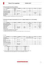
Recommended operating conditions Parameter Supply voltage I2C bus pull-up High level input voltage Low level input voltage Bus capacitance Clock frequency Resolution Symbol Vdd(A) Vdd(D) Vbus Vih Vil Cbus Fclk - *2: The pull-up resistance is determined by the Cbus and Vbus values. Electrical and optical characteristics [Ta=25 °C, Vdd(A)=Vdd(D)=3.3 V, CLK=50 MHz] Sensor area Parameter Symbol Condition Min. Typ. Spectral response range λ 440 to 1000 800 Peak sensitivity wavelength λp Current consumption 9.3 Icc Photosensitivity*3 RES 15600 Output value*4 Vor When dark -6000 0 Output value Vsat...
Open the catalog to page 2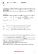
SPI area Only the data output function is used for the SPI. Parameter SPI clock frequency High level output voltage Low level output voltage High level input voltage Low level input voltage SPI data format Number of readout bits Ndata_counter Which iteration the data was read out 41 42-48 Dark frame Operation flag Dummy data 1: Dark frame All zeros 0: LED light emission frame MSB first for all data For Ch1 data, the first bit is the MSB, and the 16th bit is the LSB. DRDY CS SPCLK SPDATA From the completion of ADC conversion to the rising edge of DRDY From the rising edge of DRDY to the falling edge...
Open the catalog to page 3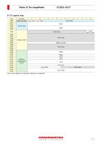
Function Sensor control r_seq_ dark_frame fixed value fixed value Analog control Ndata_counter fixed value Nlight Ndata VTX1 VTX2 Distance measurement control fixed value pres_width Fixed value registers are operation settings for ran
Open the catalog to page 4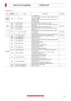
Register table Mode Global control Register address Description 1: ADC reset on The internal register is reset to its initial condition, and operation is stopped. Operation starts when ADC reset is set to ON once and then set to OFF. 0: ADC reset off ADC output result on the data1 side, 16-bit Signed 16-bit integer with the most significant bit being the sign bit ADC output result on the data2 side, 16-bit Signed 16-bit integer with the most significant bit being the sign bit Light frame (with L_trig) or dark frame (without L_trig) 1: Dark frame 0: Light frame Which data readout iteration this...
Open the catalog to page 5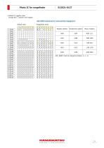
Register address Hexadecimal notation Binary notation ADC_RESET must be changed as follows: 0→1→0.
Open the catalog to page 6
Flowchart 1. Power on 2. Power on reset, initialize 3. ADC reset enable 4. Measurement condition setting 5. ADC reset disable 6. Pixel reset 8. A/D conversion, register storage 12. A/D conversion, register storage Was data read out the number of times specified by Ndata? Yes Was data read out the number of times specified by Ndata? Yellow indicates operations performed by the user, and blue the product’s internal operation. When the IC receives power and CLK, the built-in power-on reset circuit operates to set all registers to their initial conditions (2). To enter measurement conditions, enter...
Open the catalog to page 7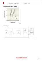
Spectral response (typical example) (Ta=25 °C) Relative sensitivity (%) Block diagram IC timing circuit TOF sensor Microcontroller FPGA
Open the catalog to page 8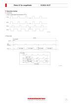
Operation timing L_trig timing L_trig is a pulse signal synchronized to VTX1. L_trig Timing chart 1 frame p_res(width) p_res VTX enable L_res VTX1 width VTX1 VTX2 width VTX2 VTX3 width VTX3 VTX enable KPICC0280EA
Open the catalog to page 9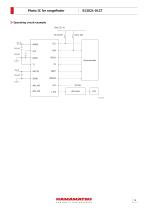
Operating circuit example Vdus (3.3 V) SPCLK Microcontroller
Open the catalog to page 10
Dimensional outline (unit: mm) 8.0 Index mark Index mark Tolerance unless otherwise noted: ±0.1 Chip position accuracy with respect to package dimensions marked * X, Y≤±0.2, θ≤±0.2 Values in parentheses indicate reference values. KPICA0099EA Recommended land pattern (unit: mm) 6.0 1.0
Open the catalog to page 11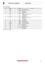
Symbol Vdd(A) Vref AGND T1 CLK SPCLK SDA SCL L_trig Add_sel1 Add_sel2 DGND NC Vdd(D) NC AGND NC Function Power supply Analog Power supply Digital Digital Description Analog supply voltage Internal reference voltage Analog ground Test terminal Master clock input SPI clock Negative data standby output Digital 0: Not standby 1: Data standby Digital SPI data output Negative chip selection input Digital 0: Selected 1: Not selected Digital I2C data (SDA) Digital I2C clock (SCK) Digital Optical pulse trigger Digital I2C address switch flag Digital I2C address switch flag Power supply Digital ground No...
Open the catalog to page 12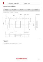
Standard packing specifications Reel Dimensions Tape width Electrostatic characteristics Conductive Embossed tape (unit: mm, material: PS, conductive) Reel feed direction Packing quantity 1000 pcs/reel Packing type Reel and desiccant in moisture-proof packaging (vacuum-s
Open the catalog to page 13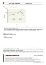
Recommended soldering conditions 300 °C 240 °C max. ∙ This product supports lead-free soldering. After unpacking, store it in an environment at a temperature of 30 °C or less and a humidity of 60% or less, and perform soldering within 24 hours. ∙ The effect that the product receives during reflow soldering varies depending on the circuit board and reflow oven that are used. When you set reflow soldering conditions, check that problems do not occur in the product by testing out the conditions in advance. Related information www.hamamatsu.com/sp/ssd/doc_en.html Precautions ∙ Disclaimer ∙ Surface mount...
Open the catalog to page 14All HAMAMATSU catalogs and technical brochures
 PHOTON COUTING HEAD
4 Pages
 SPAD MODULES
5 Pages
 LIGHTNINGCURE
29 Pages
 Xenon Flash Lamps
19 Pages
 ORCA-FUSION C14440-20UP
12 Pages
 NanoZommer series
8 Pages
 C13410 series
4 Pages
 C13410-06A
4 Pages
 PMA-12
8 Pages
 L12542
4 Pages
 FLAT EXCIMER
16 Pages
 OPTICAL PINHOLE INSPECTION UNITS
20 Pages
 Optical Gauge series
23 Pages
 L15208-01
3 Pages
 Pulsed Fiber Laser L15187
3 Pages
 L15856-01
3 Pages
 L14001-01
2 Pages
 L11854-336-05
2 Pages
 L14351-02
4 Pages
 LIGHTNINGCURE LC-L1V5
4 Pages
 GC-113A
2 Pages
 Infrared LED L14337-0085R
4 Pages
 Infrared LED L12509 series
9 Pages
 InGaAs camera C12741-11
2 Pages
 InGaAs camera C12741-03
2 Pages
 IMAGEMX2 series
8 Pages
 ORCA-Flash4.0V3 C13440-20CU
4 Pages
 ORCA-Fusion BT
9 Pages
 DIUTHAME
12 Pages
 J12853
2 Pages
 J12432-01
2 Pages
 J10919 SERIES
2 Pages
 Si APD S14644 series
6 Pages
 C15780-401
4 Pages
 CMOS area image sensor S14501
15 Pages
 H15460-40
4 Pages
 R14755U-100
2 Pages
 MPPC modules C14556 series
5 Pages
 InGaAs APD G14858-0020AA
4 Pages
 Si APD S14124-20
3 Pages
 Si strip detector S13804
3 Pages
 Si photodiode S15289-33
4 Pages
 Si PIN photodiode S15137
4 Pages
 Si PIN photodiode S14605
3 Pages
 Si PIN photodiode S13993
3 Pages
 Si photodiodes S12915 series
4 Pages
 Si photodiode S12742 series
4 Pages
 Si photodiodes S12698 series
5 Pages
 Si PIN photodiode S12271
4 Pages
 Si photodiode S10625-01CT
5 Pages
 Si photodiode S10043
3 Pages
 Si photodiode S9981-01CT
5 Pages
 Si photodiode S9674
5 Pages
 Si photodiodes S9055 series
4 Pages
 Si PIN photodiode S8650
3 Pages
 Si photodiode S8559
3 Pages
 Si photodiodes S8552, S8553
4 Pages
 Si photodiode 8193
3 Pages
 Si photodiode S7686
4 Pages
 Si PIN photodiode S7478
4 Pages
 Si PIN photodiode S4707-01
3 Pages
 Si PIN photodiode S3994-01
3 Pages
 Si PIN photodiode S3759
4 Pages
 Si photodiode S2551
4 Pages
 Si photodiodes S2387 series
4 Pages
 Si photodiodes S2386 series
4 Pages
 Si photodiodes S2281 series
3 Pages
 Si photodiode S1787 series
3 Pages
 Si photodiodes S1337 series
6 Pages
 Si photodiodes S1336 series
6 Pages
 Si photodiodes S1227 series
5 Pages
 Si photodiodes S1226 series
6 Pages
 Si photodiode 16008-33
4 Pages
 Si PIN photodiode S13337-01
4 Pages
 C13398 series
5 Pages
 InGaAs Image sensors
17 Pages
 Thermopile detector T15770
3 Pages
 CMOS linear image sensor S14772
18 Pages
 Si APD S14645 series
6 Pages
 Si APD S14643-02
6 Pages
 One-dimensional PSD S14241
5 Pages
 MEMS mirror S13989-01H
9 Pages
 MEMS mirror S13124-01
10 Pages
 PHOTOMULTIPLIER TUBE R14657
2 Pages
 PHOTON COUNTING HEAD H12775
2 Pages
 MPPC® modules C14452 series
5 Pages
 MEMS-FPI spectrum sensor C14273
11 Pages
 Photodiode modules C10439 series
13 Pages
 Phototransistor S2829
4 Pages
 InGaAs APD G8931 series
4 Pages
 Hamamatsu News 2017 Vol. 1
36 Pages
 Hamamatsu News 2017:Cover Story
36 Pages
 Photomultiplier Tube Modules
76 Pages
 LIGHT SOURCES
23 Pages
 PHOTOTUBES
8 Pages
 FLAME SENSOR UVTRON
4 Pages
 Opto-semiconductor Modules
28 Pages
 PSD
PSD8 Pages
 InGaAs Photodiodes
20 Pages
 Infrared Detectors
36 Pages
 Photo IC
8 Pages
 Image Sensors
48 Pages
 Si Photodiodes
48 Pages
 Si APD
16 Pages
 MPPC®, MPPC modules
34 Pages
 Photonic Devices
44 Pages
 IMAGE INTENSIFIERS
20 Pages
 THERMOELECTRIC COOLED
4 Pages
 FLOW CELLS
4 Pages
 COMPACT HIGH VOLTAGE
2 Pages
 SCANBLOCK C10516
4 Pages
 Immunochromato-Reader C10066
4 Pages
 UV TRONR DRIVING
2 Pages
 PULSE DELAY GENERATOR C10149
4 Pages
 High sensitivity
2 Pages
 FOP (FIBER OPTIC PLATE)
3 Pages
 20 W XENON FLASH LAMP
4 Pages
 UV POWER METERS C6080 SERIES
2 Pages
 Si photodiodes
41 Pages
 Digital CCD Cameras, ORCA-HR
2 Pages


Archived catalogs
 PHOTOSENSOR AMPLIFIER
7 Pages
 FLAT PANEL TYPE
4 Pages
 Microfocus X-ray Sources
2 Pages
 Digital CCD Camera ORCA-HR
2 Pages
 EM-TDI CCD Camera C9100-03
2 Pages
 Infrared LED L10596-02
4 Pages
 Opto-semiconductor Catalog
38 Pages
 2008 Photonic Devices Catalog
32 Pages


- Digital imager
- Visible imager
- CMOS camera module
- Industrial camera module
- ERLO measuring system
- Monitoring camera system
- Full-color camera system
- Microscope
- ERLO screener
- Spectrometer
- USB camera module
- Optical microscope
- Compact imager
- Inspection system
- Inspection imager
- Laboratory microscope
- Photoelectric sensor
- Automatic measurement system
- Optical measurement system
- Rectangular photoelectric sensor