MEMS mirror S13124-01
1 /10Pages

MEMS mirror S13124-01
1 /10Pages
Catalog excerpts

Si photodiode MEMS mirror S13124-01 Miniature, high performance, linear mode Electromagnetically driven two-dimensional laser scanning MEMS mirror The S13124-01 is an electromagnetically driven mirror that incorporates our unique MEMS (micro-electro-mechanical systems) technology. The device was made smaller by arranging the magnet beneath the mirror. A two-dimensional scanning was achieved in linear mode. Electrical current flowing in the coil surrounding the mirror produces a Lorentz force based on Fleming’s rule that drives the mirror. Hamamatsu MEMS mirrors offer a wide optical deflection angle and high mirror reflectivity. Two-dimensional scanning in linear mode Capable of vector scanning and step operation Machine vision Laser material processing Low voltage drive: suitable for installation on equipment Various laser scan units Laser measurement With window material: Prevents foreign matter contamination Evaluation circuit available: C15087 (sold separately) Structure and principle In a MEMS mirror, a metallic coil is formed on a single-crystal silicon, a mirror is formed inside the coil through MEMS processing, and a magnet is arranged beneath the mirror. Within a magnetic field generated by the magnet, electrical current flowing in the coil surrounding the mirror produces a Lorentz force based on Fleming’s rule that causes the mirror to tilt. In addition, the mirror can be driven two-dimensionally with the combination of two springs formed by MEMS processing. The path of the laser light incident on the mirror surface is varied in this way to scan and project. Compared to the electrostatic or piezoelectric driven mirrors, electromagnetically driven MEMS mirrors are lower voltage driven and easier to use. Structure diagram Laser light Magnet Magnetic field KOTHC0058EB
Open the catalog to page 1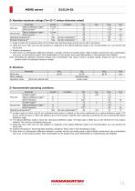
MEMS mirror Absolute maximum ratings (Ta=25 °C unless otherwise noted) Parameter Optical deflection angle*1 First axis Drive current*2 Optical deflection angle*1 Second axis Drive current*2 Operating temperature*3 Storage temperature*3 Symbol θ1 max I1 θ2 max I2 Topr Tstg *1: Angle at which the torsional stress of the torsion bars becomes large and the service life is shortened *2: Using the mirror with only one side (positive or negative) of the optical deflection angle is not recommended, as it can shorten the service life. *3: Ambient temperature *4: When there is a temperature difference between...
Open the catalog to page 2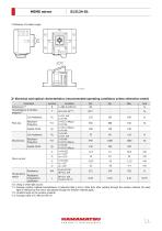
MEMS mirror Definition of incident angle Electrical and optical characteristics (recommended operating conditions unless otherwise noted) Parameter Reflectance*10 Transmittance of window material*11 Coil resistance Resonant frequency Quality factor Coil resistance First axis Resonant frequency Quality factor Second axis Drive current Temperature Resistance sensor temperature coefficient *10: Using a white light source *11: Average window material transmittance of polarized light p and s. Note that, after passing through the window material, the laser light is reflected by the mirror and passes through...
Open the catalog to page 3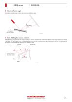
MEMS mirror Optical deflection angle The optical deflection angle is twice the mechanical deflection angle. 8° (Optical deflection angle) 4° (Mechanical deflection angle) Effect of tilting the window material The S13124-01 is equipped with the window material in order to prevent foreign matter from adhering to the mirror section. The window material tilt (20° with respect to the first axis scanning direction) is set so that the laser light reflected from the front or rear surface of the window does not enter the mirror scanning projection range. Scan light Incident light Reflected light from the...
Open the catalog to page 4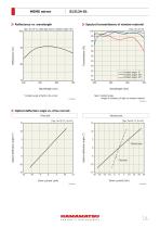
MEMS mirror Spectral transmittance of window material (Typ. Ta=25 °C, white light source, incident angle*=8°) Incident angle: 0° Incident angle: 30° Incident angle: 45° * Incident angle of light to the mirror Note: Incident angle =Angle of incidence of light on window material Optical deflection angle vs. drive current First axis Optical deflection angle (°) Optical deflection angle (°)
Open the catalog to page 5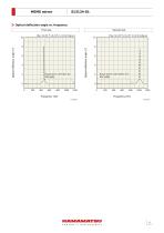
MEMS mirror Optical deflection angle vs. frequency First axis Second axis Optical deflection angle (°) Optical deflection angle (°) Range shown with broken line: Not usable Range shown with broken line: Not usable
Open the catalog to page 6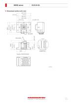
MEMS mirror Dimensional outline (unit: mm) 33.5 ± 0.15 2.5 ± 0.1 Mirror surface Connection Temperature sensor (+) First axis coil (+) Second axis coil (+) First axis coil (-) Second axis coil (-) Temperature sensor
Open the catalog to page 7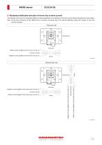
MEMS mirror Mechanical deflection direction of mirror due to drive current The direction of the mirror’s mechanical deection varies depending on the direction of the drive current owing through the coil as follows. Note: As the drive frequency of the MEMS mirror increases, the phase lag of the optical deection angle with respect to the drive current increases. First axis coil Second axis First axis Positive current applied to the first axis coil (pin ) No drive current Negative current applied to the first axis coil (pin ) No drive current Positive current applied to the second axis coil (pin...
Open the catalog to page 8
MEMS mirror Precautions ∙ See "Metal, ceramic, plastic package products / Precautions." ∙ A powerful magnet is inside the product. Bringing a magnetic body close to the product may damage the product. Therefore, we recommend using nonmagnetic screws and screwdrivers when fixing the product in place. ∙ Do not use in a strong magnetic field environment. The operating characteristics of the product may degrade due to the magnetic field. ∙ When carrying several products together, prevent each product from making contact with each other due to the attraction force of magnets, such as by fixing the products...
Open the catalog to page 9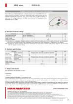
MEMS mirror Evaluation circuit for MEMS mirror C15087 (sold separately) The C15087 is a circuit board designed to simply evaluate linear mode MEMS mirror (1D: S12237-03P, 2D: S13124-01). First axis or second axis (linear mode) is driven with the selection from triangular wave, sine wave, or any chosen wave. A USB 2.0 interface is used to set the driving conditions of the MEMS mirror from the PC. This product can be driven with USB bus power. Absolute maximum ratings Parameter Operating temperature Storage temperature Supply voltage Current consumption *14: When there is a temperature difference...
Open the catalog to page 10All HAMAMATSU catalogs and technical brochures
 PHOTON COUTING HEAD
4 Pages
 SPAD MODULES
5 Pages
 LIGHTNINGCURE
29 Pages
 Xenon Flash Lamps
19 Pages
 ORCA-FUSION C14440-20UP
12 Pages
 NanoZommer series
8 Pages
 C13410 series
4 Pages
 C13410-06A
4 Pages
 PMA-12
8 Pages
 L12542
4 Pages
 FLAT EXCIMER
16 Pages
 OPTICAL PINHOLE INSPECTION UNITS
20 Pages
 Optical Gauge series
23 Pages
 L15208-01
3 Pages
 Pulsed Fiber Laser L15187
3 Pages
 L15856-01
3 Pages
 L14001-01
2 Pages
 L11854-336-05
2 Pages
 L14351-02
4 Pages
 LIGHTNINGCURE LC-L1V5
4 Pages
 GC-113A
2 Pages
 Infrared LED L14337-0085R
4 Pages
 Infrared LED L12509 series
9 Pages
 InGaAs camera C12741-11
2 Pages
 InGaAs camera C12741-03
2 Pages
 IMAGEMX2 series
8 Pages
 ORCA-Flash4.0V3 C13440-20CU
4 Pages
 ORCA-Fusion BT
9 Pages
 DIUTHAME
12 Pages
 J12853
2 Pages
 J12432-01
2 Pages
 J10919 SERIES
2 Pages
 Si APD S14644 series
6 Pages
 C15780-401
4 Pages
 CMOS area image sensor S14501
15 Pages
 H15460-40
4 Pages
 R14755U-100
2 Pages
 MPPC modules C14556 series
5 Pages
 Photo IC for rangefinder
14 Pages
 InGaAs APD G14858-0020AA
4 Pages
 Si APD S14124-20
3 Pages
 Si strip detector S13804
3 Pages
 Si photodiode S15289-33
4 Pages
 Si PIN photodiode S15137
4 Pages
 Si PIN photodiode S14605
3 Pages
 Si PIN photodiode S13993
3 Pages
 Si photodiodes S12915 series
4 Pages
 Si photodiode S12742 series
4 Pages
 Si photodiodes S12698 series
5 Pages
 Si PIN photodiode S12271
4 Pages
 Si photodiode S10625-01CT
5 Pages
 Si photodiode S10043
3 Pages
 Si photodiode S9981-01CT
5 Pages
 Si photodiode S9674
5 Pages
 Si photodiodes S9055 series
4 Pages
 Si PIN photodiode S8650
3 Pages
 Si photodiode S8559
3 Pages
 Si photodiodes S8552, S8553
4 Pages
 Si photodiode 8193
3 Pages
 Si photodiode S7686
4 Pages
 Si PIN photodiode S7478
4 Pages
 Si PIN photodiode S4707-01
3 Pages
 Si PIN photodiode S3994-01
3 Pages
 Si PIN photodiode S3759
4 Pages
 Si photodiode S2551
4 Pages
 Si photodiodes S2387 series
4 Pages
 Si photodiodes S2386 series
4 Pages
 Si photodiodes S2281 series
3 Pages
 Si photodiode S1787 series
3 Pages
 Si photodiodes S1337 series
6 Pages
 Si photodiodes S1336 series
6 Pages
 Si photodiodes S1227 series
5 Pages
 Si photodiodes S1226 series
6 Pages
 Si photodiode 16008-33
4 Pages
 Si PIN photodiode S13337-01
4 Pages
 C13398 series
5 Pages
 InGaAs Image sensors
17 Pages
 Thermopile detector T15770
3 Pages
 CMOS linear image sensor S14772
18 Pages
 Si APD S14645 series
6 Pages
 Si APD S14643-02
6 Pages
 One-dimensional PSD S14241
5 Pages
 MEMS mirror S13989-01H
9 Pages
 PHOTOMULTIPLIER TUBE R14657
2 Pages
 PHOTON COUNTING HEAD H12775
2 Pages
 MPPC® modules C14452 series
5 Pages
 MEMS-FPI spectrum sensor C14273
11 Pages
 Photodiode modules C10439 series
13 Pages
 Phototransistor S2829
4 Pages
 InGaAs APD G8931 series
4 Pages
 Hamamatsu News 2017 Vol. 1
36 Pages
 Hamamatsu News 2017:Cover Story
36 Pages
 Photomultiplier Tube Modules
76 Pages
 LIGHT SOURCES
23 Pages
 PHOTOTUBES
8 Pages
 FLAME SENSOR UVTRON
4 Pages
 Opto-semiconductor Modules
28 Pages
 PSD
PSD8 Pages
 InGaAs Photodiodes
20 Pages
 Infrared Detectors
36 Pages
 Photo IC
8 Pages
 Image Sensors
48 Pages
 Si Photodiodes
48 Pages
 Si APD
16 Pages
 MPPC®, MPPC modules
34 Pages
 Photonic Devices
44 Pages
 IMAGE INTENSIFIERS
20 Pages
 THERMOELECTRIC COOLED
4 Pages
 FLOW CELLS
4 Pages
 COMPACT HIGH VOLTAGE
2 Pages
 SCANBLOCK C10516
4 Pages
 Immunochromato-Reader C10066
4 Pages
 UV TRONR DRIVING
2 Pages
 PULSE DELAY GENERATOR C10149
4 Pages
 High sensitivity
2 Pages
 FOP (FIBER OPTIC PLATE)
3 Pages
 20 W XENON FLASH LAMP
4 Pages
 UV POWER METERS C6080 SERIES
2 Pages
 Si photodiodes
41 Pages
 Digital CCD Cameras, ORCA-HR
2 Pages


Archived catalogs
 PHOTOSENSOR AMPLIFIER
7 Pages
 FLAT PANEL TYPE
4 Pages
 Microfocus X-ray Sources
2 Pages
 Digital CCD Camera ORCA-HR
2 Pages
 EM-TDI CCD Camera C9100-03
2 Pages
 Infrared LED L10596-02
4 Pages
 Opto-semiconductor Catalog
38 Pages
 2008 Photonic Devices Catalog
32 Pages


- Digital imager
- Visible imager
- CMOS camera module
- Industrial camera module
- ERLO measuring system
- Monitoring camera system
- Full-color camera system
- Microscope
- ERLO screener
- Spectrometer
- USB camera module
- Optical microscope
- Compact imager
- Inspection system
- Inspection imager
- Laboratory microscope
- Photoelectric sensor
- Automatic measurement system
- Optical measurement system
- Rectangular photoelectric sensor