


INSTALLATION INSTRUCTIONS

INSTALLATION INSTRUCTIONS
This document provides comprehensive installation, operation, and maintenance instructions for HAM-LET advanced control technology components, including LET-LOK and ONE-LOK tube fittings, needle valves, check valves, and ball valves. It emphasizes proper handling, assembly, and maintenance to ensure leak-free and efficient operation.
- Ensure firm insertion of the tube and finger-tighten the nut.
- Tighten the nut 1 1/4 turns for larger sizes and 3/4 turn for smaller sizes.
- Use a tube cutter for square cuts and deburr tube ends to prevent leaks.
- Handle tubes carefully to avoid scratches.
- For reassembly, mark the nut position and tighten to the original position.
- Operate within specified pressure and temperature ranges.
- Open by rotating the handle for maximum flow; close by rotating until the stem contacts the seat.
- Clean valves used with hazardous media before disassembly.
- Replace stem seals if leakage occurs.
- Disassembly involves removing the handle and packing bolt, inspecting parts for damage.
- Use within specified pressure and temperature ranges, considering O-ring compatibility.
- Disassemble carefully if used with hazardous media, replace seats, seals, and springs if leaks occur.
- Test valves with nitrogen to ensure no leakage at specified pressures.
- Handle carefully during installation to avoid damage.
- Operate by turning the handle 1/4 turn to open or close.
- Ensure material compatibility and use within specified ranges for optimal valve life.
- Use PTFE tape on male tapered pipe threads for sealing.
- Protect sealing surfaces from damage and contamination.
- Follow clean-room protocols for high-purity applications.
- Regularly inspect and maintain components to ensure proper function and safety.
- Valves should be used within specified pressure and temperature ranges, considering material corrosion resistance.
- Adhere to operational guidelines for maximum valve life.
- Ensure valve-stem alignment to prevent high operational torque and wear.
- Decontaminate valves used in hazardous mediums before disassembly.
- Wear protective clothing during removal and disassembly.
- Follow specific instructions for replacing seats, joint gaskets, stem seals, and stem packing.
- Use Belleville washers for automatic seal wear compensation.
- Valves can be installed in any pipeline position.
- Ensure pipelines are clean and free of debris before installation.
- Use appropriate sealants and tools to avoid damage during installation.
- Threaded Valves: Use conventional sealants and avoid tightening using the valve body.
- Weld End Valves: Follow detailed steps for tack-welding and final assembly.
- Perform operations with system pressure fully relieved.
- Use appropriate tools and safety devices during maintenance.
- Designed for low-pressure applications with set pressures between 10 psig and 225 psig.
- Made from stainless steel 316, available in various connector types.
- Tested for proof, burst, and leakage, with factory testing for set and resealing performance.
- Improper selection, installation, or use can cause property damage or personal injury.
- Ensure compliance with CE marking for valves used within the European Community.
- Install the bonnet into the body and tighten to specified torque.
- Perform adjustment procedures before system installation.
- Ensure system pressure is relieved before maintenance.
- Common issues include leakage through O-Ring seals and incorrect spring force.
- Solutions involve replacing O-Rings, cleaning components, and selecting appropriate springs.
- For oxygen applications, follow specific procedures and use oxygen-clean kits.
- Clean all components before reassembly.
- Lubricate sealing gaskets with recommended oil.
- Tighten nuts to specified torque using a moment wrench.
- Check for leaks using liquid leak detectors.
- Includes Bourdon tube, diaphragm, and capsule types.
- Selection should consider application requirements and safety standards.
- Diaphragm gauges are suitable for viscous media.
- Capsule gauges are not suited for liquid pressure media.
- Bourdon tubes are used for a wide range of pressures.
- Ensure gauges have blow-out devices for safety.
- Consider ambient conditions and pressure ranges when selecting gauges.
- Avoid rapid pressure changes to prevent damage.
- Follow EN 837-1 and ASME B40.1 standards for accuracy and safety.
- Use fluid-filled gauges with blow-out devices for hazardous media.
- Ensure proper installation to avoid vibrations and temperature effects.
- Maintain correct media temperature for pressure gauges, referencing standards such as EN 837 and ASME B40.1.
- Use a sufficiently long measuring line, siphon, or chemical seal to manage temperature deviations.
- For highly viscous, crystallizing, or solids-containing media, diaphragm or Bourdon tube pressure gauges with chemical seals are recommended.
- Corrosive media require careful material selection to prevent damage to the gauges.
- In corrosive environments, corrosion-resistant materials and special surface finishes are necessary.
- Chemical seals are advised for aggressive, hot, or viscous media to protect the gauge's elastic element.
- Overpressure protection devices are recommended if the gauge's pressure range is below the maximum operating pressure.
- Holding devices should be used if the connected line cannot support the gauge without vibrations.
- Shut-off devices allow for gauge exchange and zero setting checks while the system remains operational.
- The document provides guidance on preferred setup arrangements for pressure gauges.
- Installation should be performed by skilled personnel, ensuring the gauge is not subjected to vibrations or extreme temperatures.
- Proper sealing and connection techniques are emphasized to prevent leaks and ensure accurate readings.
- Specifies usage limits for static and pulsating loads on different types of pressure gauges.
- Outlines procedures for zero and pressure range checks, emphasizing the importance of maintaining the permissible operating temperature.
- Provides information on the temperature resistance of materials, soldered joints, and welded seams.
- Highlights the importance of considering indication errors due to deviations from the reference temperature.
- Ensure the permissible operating temperature for pressure gauges is not exceeded during cleaning or purging.
- For gauges with chemical seals, adhere to the maximum cleaning temperature.
- Pressure gauges generally require no maintenance and should only be repaired by the manufacturer.
- Instruments must be cleaned before returning for repair, especially if hazardous media were used.
- Electrical connections should be made by qualified personnel.
- Adhere to load limits and safety regulations.
- Ensure cable diameters match sealing inlets, and tighten screwed joints firmly.
- Use shielded cables for DMU type pressure transducers to ensure electromagnetic compatibility.
- Store pressure gauges in original packaging, protected from damage.
- Maintain temperature limits between -40°C and +60°C.
- Pressure gauges are suitable for use in explosive areas if made of stainless steel and laminated safety glass.
- Instruments with deflagration volume protection are suitable for category-1 use, preventing flame penetration in explosive mixtures.
For additional information and technical support, contact your Ham-Let representative.
Catalog excerpts

INSTALLATION INSTRUCTIONS INSTALLATION INSTRUCTIONS
Open the catalog to page 1
SCREWED BONNET NEEDLE VALVES H-99 / H-99HP H-900 SERIES RELIEF VALVES H-400 SERIES CHECK VALVES H900-HP SERIES HIGH PRESSURE RELIEF VALVES PIPE LINE PRECISION INSTRUMENTATION PIPE FITTING H-500 SERIES 3-Piece ball valves H600 SERIES T-TYPE & IN-LINE FILTERS H-700 SERIES BALL VALVES WITH LOCKING DEVICE PRESSURE GAUGES INSTALLATION & OPERATION INSTRUCTIONS H300U SERIES. Needle valves INSTALLATION INSTRUCTIONS LET-LOK TUBE FITTINGS 1/16" THROUGH - INCH 2 MM THROUGH 25 MM METRIC H-6800 SERIES INSTRUMENTATION BALL VALVES INSTALLATION INSTRUCTIONS
Open the catalog to page 2
through 1" - Inch, 2 mm through 25 mm - Metric LET-LOK® fittings are supplied assembled and finger tight. Diassembly before use can allow the entry of dirt or other particles. 1. Insert the tubing into the LET-LOK® fitting. Check that the tube rests firmly on the fitting shoulder and that the nut is finger tight. 2. Tighten the nut. 11/4 turns of the nut are required for 1/4" (6 mm) and higher. (See Figure A.) 3/4 of a turn of the nut is required for 3/16" (4 mm) and lower. (See Figure B.) Tube Cutter To attain a leak-free connection, cut the tubing squarely. Use a good quality tube cutter with...
Open the catalog to page 3
Tube Cutting There are two ways to cut tubes: 1. Tube cutter 2. Hacksaw Tube Cutter ONE-LOK® fittings are supplied assembled and finger tight. Diassembly before use can allow the entry of dirt or other particles. 1. Insert the tubing into the ONE-LOK® fitting. Check that the tube rests firmly on the fitting shoulder and that the nut is finger tight. 2. Tighten the nut. 1 1/4 turns of the nut are required. (See Figure A.) To attain a leak-free connection, cut the tubing squarely. Use a good quality tube cutter with the appropriate blade for the tubing. Do not try to reduce the time of cutting...
Open the catalog to page 4
HAM-LET PRECISION INSTRUMENTATION PIPE FITTINGS To ensure a leak-tight seal, HAM-LET recommends that you use a pipe-thread sealant on all NPT threads. The most effective sealing method is PTFE tape. Tape should be used only on male tapered pipe threads. Do not use tape on flared, coned or tube fitting ends! Note: We suggest two wraps for stainless-steel tapered pipe threads. Make sure the tape does not overhang the first thread. Otherwise,the tape could shred and enter the fluid system. Cut off excess tape. The connection is now ready for proper makeup. Clean both male and female tapered threads....
Open the catalog to page 5
NEEDLE VALVES H-300U SERIES 1. Use For maximum valve life, use the valve only within the stated pressure and temperature range, and in accordance with the corrosion resistance of the material. Re-Assembly Reverse the steps above, taking care to lubricate all parts with an appropriate lubricant. 2. Operation To open the valve, rotate the handle until it comes in contact with the lower gland. This will allow maximum flow through the valve. To close the valve, rotate the handle until the stem tip comes into contact with the seat. Do not use excessive force when closing the valve. Excessive torque...
Open the catalog to page 6
SCREWED BONNET NEEDLE VALVES H-99 6. Installation Disassembly n On taper threads, use a conventional thread sealant such as PTFE tape or an appropriate alternative that is compatible with the application. n Apply a wrench to the body and connecting nut. Do not use the handle to tighten the connection. LET-LOK® Valves n Ensure the tubing is cut square and that it is de-burred. n Ensure the tubing is located firmly in the connection. n From the finger-tight position, rotate the nut a full 1 1/4 turn. Note: For sizes 3/16 inch (4mm) or less, rotate the nut 3/4 turn only. n Apply a wrench to the...
Open the catalog to page 7
H-400 SERIES CHECK VALVES 1. Use For maximum valve life, use the valve only within the stated pressure and temperature range, and in accordance with the corrosion resistance of the material. Give particular attention to the compatibility of the O-ring material. 2. Disassembling and Cleaning the Valve A non-return valve can trap fluids within the body. If the valve has been used in hazardous media service, remove with great care and take appropriate decontamination measures. All persons involved in the removal and disassembly of the valve should wear proper protective clothing, such as gloves,...
Open the catalog to page 8
H-500 SERIES 3-PIECE BALL VALVES 2. Manual Operation 2.1 To open or close the valve, turn the handle 1/4 of a turn (90 degrees). A. When the valve is in the Open Position, the handle is parallel (in-line) with the valve or pipeline. B. When the the valve is in the Closed Position, the handle is perpendicular (crossed) to the valve or pipeline. 3. Automated Operation 3.1 Check any valve with an actuator for valve-stem alignment. Angular or linear misalignment will result in high operational torque and unnecessary wear on the stem seal. 4. Disassembling & Cleaning of the Valve: A ball valve can...
Open the catalog to page 9
H-500 SERIES 3-PIECE BALL VALVES 6. General Information for On-Site Installation: 6.1 The valve may be fitted in any position on the pipeline. 6.2 To prevent damage to the seats and ball surface, make sure the pipeline is flushed, free of dirt, burrs and welding residues before installing the valve. INSTALLATION INSTRUCTIONS 7. Installation of Threaded Valves 7.1 Use a conventional sealant, such as a hemp core, PTFE, etc. 7.2 Apply a wrench to the hexagon end of the valve only. Tightening by using the valve body or handle can seriously damage the valve. 7.3 For applications where the screwed...
Open the catalog to page 10
H-700 SERIES BALL VALVES WITH LOCKING DEVICE 1. Use For maximum valve life, use the valve only within the stated pressure and temperature range, and in accordance with the corrosion resistance of the material. 2. Operation To open or close the valve, turn the handle 1/4 of a turn (90°). 3. Cleaning the Valve A ball valve can trap fluids in the ball cavity when it is in the closed position. If the valve has been used in the hazardous medium, decontaminate it before disassembly. All persons involved in the removal and disassembly of the valve should wear appropriate protective clothing, such as...
Open the catalog to page 11All HAM-LET catalogs and technical brochures
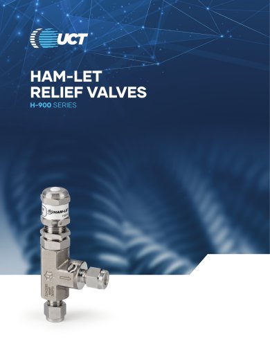 Relief Valves H-900 Series
5 Pages
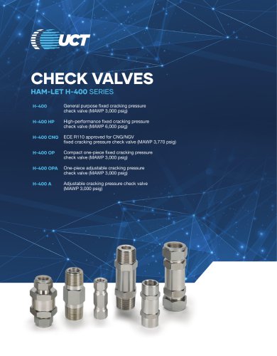 Check Valves H-400 Series
18 Pages
 Pressure Gauges
31 Pages
 High Pressure
26 Pages
 Quick Connector
8 Pages
 Pressure Regulator
76 Pages
 TOGGLE VALVES H-1200
4 Pages
 Let-Lok® Tube Fittings
94 Pages
 HTC - Hi-Tech Components
32 Pages
 2015 CATALOG EN
517 Pages
 ULTRA FAST DIAPHRAGM VALVE
6 Pages
 HAM-LET HOSE CONNECTORS
4 Pages
 VENT PROTECTOR FITTINGS VEP
2 Pages
 HAM-LET FLANGE ADAPTERS
4 Pages
 SAMPLE CYLINDERS
4 Pages
 HAM-LET Hoses
24 Pages
 UCV Ultra Clean Diaphragm Valves
22 Pages
 Ham-Let Astava Line of Manifolds
26 Pages
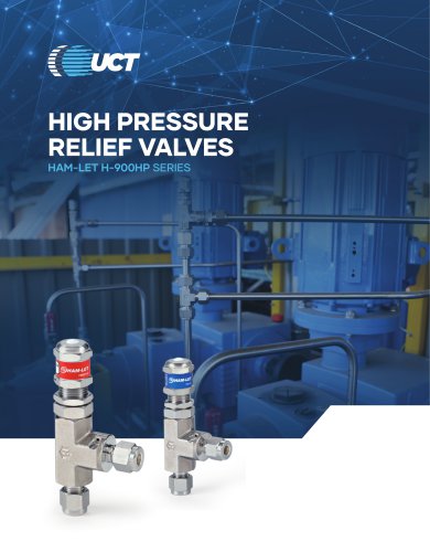




Archived catalogs
 Product at a glance
2 Pages
 H1200 Toggle Valves
4 Pages
 solar energy
4 Pages
 37° Flare Fittings
22 Pages
 H800 - Compact Ball Valves
8 Pages
 Accessories
5 Pages


