Catalog excerpts

HIGH VOLTAGE TEST Impulse Current Test Systems Type SSGA Operating Duty Test System 100 kV, 150 kJ, 150kA
Open the catalog to page 1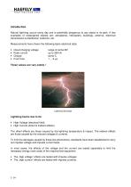
,QWURGXFWLRQ Natural lightning occurs every day and is potentially dangerous to any object in its path. A few examples of endangered objects are: aeroplanes, helicopters, buildings, antenna, electrical transmission & distribution networks, etc. Measurements have shown the following basic electrical data: • • • • Cloud charging voltage Peak current Charge Front time range of some MV up to 350 kA some C 1 ... 6 µs /LJKWQLQJ GLVFKDUJH /LJKWQLQJ KDUPV GXH WR LWV • High Voltage (electrical field) • High Current (direct & indirect effects) The GLUHFW HIIHFWV are those caused by the lightning...
Open the catalog to page 2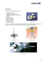
$SSOLFDWLRQV The main applications are the testing of: • Arrestors and varistors • Building protection elements • Aeroplanes, helicopters, wind generator blades, etc. • Research • Testing of breakers • EMP & NEMP tests • Military applications • Feeding of Lasers • Plasma applications $UUHVWRU GLVFV Our primary customers for our impulse current generators are the manufacturers of arrestors and varistors. Test systems for the other applications can also be offered upon request. &DSWXULQJ KHDG
Open the catalog to page 3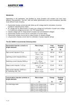
6WDQGDUGV Depending on the application, test facilities for surge arresters and varistors can have many different characteristics. The IEC, VDE and ANSI specifications and recommendations describe many different tests including: • Exponential impulse current test with follow-up AC voltage load for simulation of service conditions (Operating Duty Tests). • AC voltage test for determination of spark-over voltage and verification of spark-over voltage or of reference voltage and current, incl. PD measurement. • Impulse voltage test for measurement of spark-over and withstand voltages •...
Open the catalog to page 4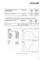
HIGH VOLTAGE TEST Data of impulse generator Typical 8/20 jus wave shape simulation
Open the catalog to page 5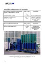
7KHUHIRUH ZKLFK LPSXOVH FXUUHQWV DUH PRVW RIWHQ QHHGHG " 7HVW RQ DUUHVWRU VHFWLRQV LQ IDFWRU\ PDWHULDO VDPSOHV EXLOGLQJ SURWHFWLRQ HOHPHQWV Exponential impulse currents Impulse current generator Long duration impulse currents Impulse current generator Operating Duty Tests Impulse current generator with special AC test equipment Impulse voltage generator with impulse current generating elements. 7HVW RQ FRPSOHWH DUUHVWRUV RQVLWH Lightning current impulse 8/20 µs /RQJ GXUDWLRQ PV WHVW V\VWHP N9 N- ZLWK HDUWKLQJ V\VWHP DW ULJKW DQG KLJK FXUUHQW FKDUJLQJ UHFWLILHU N9 P$ DW OHIW
Open the catalog to page 6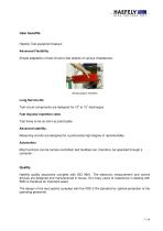
8VHU EHQHILWV Haefely Test equipment feature: $GYDQFHG )OH[LELOLW\ Simple adaptation of test circuit to test objects of various impedances. +DQG\ SOXJLQ UHVLVWRUV /RQJ 6HUYLFH OLIH Test circuit components are designed for 106 to 107 discharges. )DVW ,PSXOVH UHSHWLWLRQ UDWHV Test times to be as short as practicable. $GYDQFHG VWDELOLW\ Measuring circuits are designed for a particularly high degree of reproducibility. $XWRPDWLRQ Most functions can be remote controlled; test facilities can, therefore, be operated through a computer. 4XDOLW\ Haefely quality assurance complies with ISO 9001. The...
Open the catalog to page 7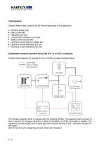
7HVW V\VWHPV Several different test systems can be offered depending of the application: • • • • • • • • Residual voltage test High current test Operating duty test Long-duration impulse current test Steep current impulse test Lightning current residual voltage test Lightning current operating duty test Switching current operating duty test ([SRQHQWLDO FXUUHQW RQ DUUHVWRU GLVFV ZLWK PV RU PV LPSXOVHV A typical block-diagram for typically 4/10 µs or 8/20 µs pulses is shown below: Control cables Power connections Measuring cables Test object Charging rectifier Impulse generator Current sensor...
Open the catalog to page 8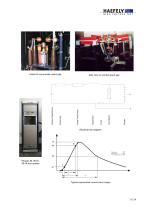
6LGH YLHZ RQ FHQWUDO VSDUN JDS 'HWDLO RI D SQHXPDWLF VSDUN JDS (OHFWULFDO OLQH GLDJUDP ± 10% Peak value: ± 10% Front time T1: Time to half value T2:± 10% 7\SLFDO H[SRQHQWLDO FXUUHQW ZDYH VKDSH
Open the catalog to page 9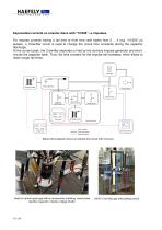
([SRQHQWLDO FXUUHQWV RQ DUUHVWRU GLVFV ZLWK ³´ PV LPSXOVHV For impulse currents having a tail time to front time ratio higher than 2 ... 3 (e.g. “10/350” µs pulses), a Crow-Bar circuit is used to change the circuit time constants during the capacitor discharge. At the current peak, the Crow-Bar electrode is fired by the auxiliary impulse generator and shortcircuits the capacitor bank. Thus, the time constant for the impulse tail increases, which allows to reach longer tail times. Test object Impulse generator Charging rectifier Current sensor Voltage divider Crow-bar Sphere gap Impulse...
Open the catalog to page 10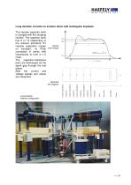
/RQJ GXUDWLRQ FXUUHQWV RQ DUUHVWRU GLVFV ZLWK UHFWDQJXODU LPSXOVHV ' + 20% , - 0% Peak value: Duration of the peak Td:+ 20% , - 0% /RQJ GXUDWLRQ LPSXOVH FRQILJXUDWLRQ (OHFWULFDO OLQH GLDJUDP The impulse capacitor bank . is charged with the charging rectifier. The capacitor bank has 8 or 10 (depending of the relevant standard) HV 7\SLFDO impulse capacitors (castor ZDYH VKDSH oil insulated, no PCB) connected in series with inductances to form a L-C chain. The capacitor-inductance pairs are discharged via the spark gap through the test object. Both the current and voltage signals and values...
Open the catalog to page 11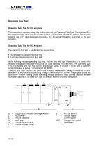
2SHUDWLQJ 'XW\ 7HVW 2SHUDWLQJ 'XW\ 7HVW IRU 6L& DUUHVWHUV The basic circuit diagram shows the configuration of the Operating Duty Test. The arrester (P) is first exposed to the rated impulse current which is synchronised with the AC voltage. Because the isolating gap (SF) also becomes conductive, the AC current must be quenched in the zero transition. 2SHUDWLQJ 'XW\ 7HVW IRU 02 $UUHVWHUV The operating duty test is subdivided into two sections: • Switching impulse operating duty test • Lightning impulse operating duty test In the lightning impulse operating duty test, the first step with...
Open the catalog to page 12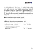
HIGH VOLTAGE TEST The Switching Impulse Operating Duty Test is similar to the description of the lightning impulse operating duty test. The first step is to conduct the residual voltage and the conditioning or high- current tests. Prior to the actual operating duty test, the arrester must have a temperature of 60 ±30°C. The two following long duration current impulses depend on the arrester class. Immediately after the second impulse (not later than 100 ms), the AC voltage is switched on as in the case of the lightning operating duty test. Arrester cooling must also be checked under...
Open the catalog to page 13All Haefely AG catalogs and technical brochures
-
DDX 9160/9161
11 Pages
-
VITAS 2772
4 Pages
-
CITAS 2771
4 Pages
-
2763 / 2767 / 2769
6 Pages
-
AXOS
7 Pages
-
PGR
4 Pages
-
CTTS Series
8 Pages
-
KIT 4.0
10 Pages
-
PSURGE 30.2
4 Pages
-
MAG 1000
8 Pages
-
MIDAS micro 2883
6 Pages
-
TTR 2796
5 Pages
-
PCI 811c
4 Pages
-
ACS
7 Pages
-
2903
4 Pages
-
3695
3 Pages
-
NK SERIES, 3370
4 Pages
-
2767
4 Pages
-
High Voltage Construction KIT
28 Pages
-
UHVDC - Applied DC Testing
4 Pages
-
DEC 5
2 Pages
-
5478
2 Pages
-
5289
1 Pages
-
5288A
1 Pages
-
5250
2 Pages
-
4762 Range Extender
1 Pages
-
3320 2 kV
2 Pages
-
2914 Solid Test Cell
3 Pages
-
2903 Oil Test Cell
2 Pages
-
2840
4 Pages
-
2830/2831
4 Pages
-
2820a
4 Pages
-
260 DC
2 Pages
-
2293
4 Pages
-
2226a
2 Pages
-
TSS
20 Pages
-
CTT & WPU
8 Pages
-
USG 40
2 Pages
-
RM 430
2 Pages
-
PSK
20 Pages
-
R 500 REF, RCZ 500 REF
2 Pages
-
RIC 422
4 Pages
-
RSG 482
3 Pages
-
DMI 551
2 Pages
-
DiAS® 733
6 Pages
-
HiAS® 743
7 Pages
-
KFS
2 Pages
-
MAFS
2 Pages
-
GC 257
6 Pages
-
GC 223
4 Pages
-
SH-H, SH-Q, SH-R
2 Pages
-
DTTS
8 Pages
-
Global Services
8 Pages
-
RSKF
4 Pages
-
Partial Discharge
24 Pages
-
Portable Instruments
13 Pages
-
Product Overview Tettex
20 Pages
-
ONYX ESD simulator
8 Pages
-
Product Overview 2013
24 Pages
-
AXOS 8
20 Pages


