MAFS
1 /2Pages

MAFS
1 /2Pages
Catalog excerpts

Multiple Chopping Gap The multiple chopping gap is a originally patented Haefely development and is used to chop lightning impulses (on the front and on the tail) as well as switching impulses up to the highest voltages. The sphere distance is automatically adjusted by the controls GC 223, GC 257. In the automatic mode, their distance is set automatically in function of the charging voltage. The gap distance is displayed on these controls. The chopping is initiated by the first stage, having a triggering plug. The multiple chopping gap serves simultaneously as a load capacitor for the impulse generator and allows excellent reproducibility of the chopping time and does not distort the wave shape until the chopping point. A manual control box GSC 219 is available to adjust the gap distance standalone or with non-Haefely control systems. With a additional secondary unit the MAFS is also usable for some applications as a voltage divider. Rod gaps and sphere gaps (above 1000 kV) draw a substantial pre-discharge current prior to the voltage break-down, causing a voltage drop. This affects the comparison tests when testing power transformers. Design For indoor operation and mobile design. The HV units are made of stacked capacitors with inserted damping resistances. This active part is built in reinforced fibre-glass cylinders. Our active part technology is derived from our decadelong experience. The copper spheres have tungsten sintered inserts to reduce the burn-off. Their distance is set by a precise drive. The upper semi-sphere is attached to a movable frame which makes it possible to adjust simultaneously all partial spark gaps. The multiple chopping gaps are equipped with toroid electrodes. The electrodes are made of brushed aluminium. The electrode type is determined by the rated voltage. Fibre-glass struts are required when more than 2400 kV units are used. The H base frame of welded steel profiles is equipped with four swivel castors. Multiple chopping gap MAFS in front of an SGDA Multiple chopping gap MAFS 2400 Subject to change without notice.
Open the catalog to page 1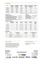
Technical Data Type Rated impulse Rated impulse Capacitance Int. damping Min. clearance to Top electrode voltage LI voltage SI approx. resistance walls and ceiling type at standard conditions according to IEC 60060-1 (1989) and altitudes lower than 1000 m. Trigger range General for time-to-chop scattering: < ± 150ns Relative humidity <90% non-condensing for unchanged gap spacing, negative polarity approx. 20 % Operating temperature -5 ... + 45°C for unchanged gap spacing, positive polarity approx. 10 % Storage temperature - 20 ... + 50 °C with variable gap setting, both polarities 30 % to 100...
Open the catalog to page 2All Haefely AG catalogs and technical brochures
 DDX 9160/9161
11 Pages
 VITAS 2772
4 Pages
 CITAS 2771
4 Pages
 2763 / 2767 / 2769
6 Pages
 AXOS
AXOS7 Pages
 PGR
PGR4 Pages
 CTTS Series
8 Pages
 KIT 4.0
10 Pages
 PSURGE 30.2
4 Pages
 MAG 1000
8 Pages
 MIDAS micro 2883
6 Pages
 TTR 2796
5 Pages
 PCI 811c
4 Pages
 ACS
ACS7 Pages
 2903
29034 Pages
 3695
36953 Pages
 NK SERIES, 3370
4 Pages
 2767
27674 Pages
 High Voltage Construction KIT
28 Pages
 UHVDC - Applied DC Testing
4 Pages
 DEC 5
DEC 52 Pages
 5478
54782 Pages
 5289
52891 Page
 5288A
5288A1 Page
 5250
52502 Pages
 4762 Range Extender
1 Page
 3320 2 kV
2 Pages
 2914 Solid Test Cell
3 Pages
 2903 Oil Test Cell
2 Pages
 2840
28404 Pages
 2830/2831
4 Pages
 2820a
2820a4 Pages
 260 DC
2 Pages
 2293
22934 Pages
 2226a
2226a2 Pages
 TSS
TSS20 Pages
 CTT & WPU
8 Pages
 SSGA 100-150
24 Pages
 USG 40
2 Pages
 RM 430
2 Pages
 PSK
PSK20 Pages
 R 500 REF, RCZ 500 REF
2 Pages
 RIC 422
4 Pages
 RSG 482
3 Pages
 DMI 551
2 Pages
 DiAS® 733
6 Pages
 HiAS® 743
7 Pages
 KFS
KFS2 Pages
 GC 257
6 Pages
 GC 223
4 Pages
 SH-H, SH-Q, SH-R
2 Pages
 DTTS
DTTS8 Pages
 Global Services
8 Pages
 RSKF
RSKF4 Pages
 Partial Discharge
24 Pages
 Portable Instruments
13 Pages
 Product Overview Tettex
20 Pages
 ONYX ESD simulator
8 Pages
 Product Overview 2013
24 Pages
 AXOS 8
20 Pages


- Measuring machine
- AMOT calibrator
- AMOT automatic tester
- AMOT industrial tester
- AMOT power transformer
- Automatic test kit
- AMOT voltage tester
- Test set
- AMOT industrial testing device
- AMOT ceramic capacitor
- AMOT resistance tester
- AMOT compact tester
- AMOT electrical installation tester
- Immersed transformer
- Indoor service transformer
- AMOT multifunction tester
- AMOT voltage capacitor