Group: HUBBELL INC

Catalog excerpts
HIGH VOLTAGE TEST
Open the catalog to page 1
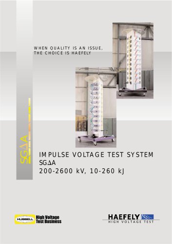
I M P U L S E V O LTA G E T E S T S Y S T E M A P P L I C AT I O N The SGSA systems can be equipped with hydraulic jacking system or mounted on a trailer for better transportability. The system is built on contains all experience acquired in impulse generator production since 1932. SGSA impulse test systems can be used to generate impulse voltages from 10 kV to 750 kV simulating lightning strokes and switching surges. The total charging voltage range covers from 100 kV to 800 kV with a stage energy of 5 kJ. • total charging voltage from 100 kV up to 800 kV (optional up to 1200 kV) • 5 kJ...
Open the catalog to page 2
QUALITY USER BENEFITS Quality Compact Design The electronic measurement and control components are designed and manufactured inhouse. Our many years of experience in dealing with electromagnetic compatibility of electronic devices in high voltage test bays provides the requisite expertise. Design of the impulse test system SGSA is light and flexible, for limited space and on-site purposes. For onsite tests it can be easily mounted on a trailer, specially when equipped with hydraulic jacking mechanisms. In designing and manufacturing our impulse test systems we take full advantage of our...
Open the catalog to page 3
Max. Max charging energy voltage Impulse capacitance SGSA SGSA SGSA SGSA SGSA SGSA SGSA SGSA switching impulse 250/2500 (Option) Max. output voltage at Cb max ± Upeak LI Max. output voltage at Cb max ± Upeak SI Time between impulses at Ul max t s 40 40 40 40 40 40 50 55
Open the catalog to page 4
Min. safe clearance to wall Capaci- Damping Height tance resistor Shipping volume/ weight (whole system) Impulse Voltage Test System, proposed layout Test specimen
Open the catalog to page 5
Operating Range Impulse Intervals The minimum output voltage is 10 kV independent of polarity. This is obtained with only one stage. The other stages are shorted or connected in parallel. The maximum output voltage can be read from the table. It depends on the load and the waveform. At maximum charging voltage, minimum time between impulses is given in the table SGSA system data. This interval is dictated by the maximum charging current thermal limitation of parallel resistors and the maximum energy of the impulse capacitors in the impulse generator. If the charging voltage is reduced, the...
Open the catalog to page 6
T H E I M P U L S E V O LTA G E G E N E R AT O R FUNCTION OF THE IMPULSE TEST SYSTEM The test system comprises the following main components: • • • • charging rectifier impulse generator control system divider Accessories for additional measurements, tests or analyses of the wave shape are: • shunt • chopping gap • measuring system The block diagram below demonstrates the basic functions of the system. The impulse test system operates under a control system which charges the impulse generator through the charging unit. This is achieved as the stages in the impulse generator are connected in...
Open the catalog to page 7
The Impulse Voltage Generator is the main part of an impulse voltage test system. An impulse voltage generator SGS consists of a number of capacitors charged in parallel up to a maximum voltage of 100 kV. When the desired charging voltage has been reached, a set of sphere gaps connect the capacitors in series and the output voltage is delivered via some pulse forming elements. The figure shows an equivalent circuit diagram for a single stage impulse generator (it is possible to simplify a multi stage impulse generator into this circuit). Each impulse capacitor consists of flat elements...
Open the catalog to page 8
OVERSHOOT C O M P E N S AT I O N Overshoot The most important difference between the simplified equivalent circuit and a more accurate equivalent circuit is the consideration of additional energy storage elements. RS Impulse Capacitance Spark Gap Parallel Resistance Serie Resistance Total Serie Inductance Serie Resistance Load Test Objekt External Overshoot Compensation The consequence of these additional elements is important. Discharge of the impulse capacitor can produce oscillations. If the impulse test circuit forms a resonance circuit an overshoot will be generated. According to IEC...
Open the catalog to page 9
GLANINGER CIRCUIT Realisation of Overshoot Compensation Realisation of Overshoot Compensation for impulse generators of type SGS is an external additional arrangement of components. This solution can also be used for "Non-Haefely-Generators". Impulse Capacitance Spark Gap Parallel Resistance Serie Resistance/Inductance Overshoot Compensation Test Object, Divider, MAFS (Load) The Glaninger Circuit (see figure below) can be used for testing very small inductances, such as the low-voltage windings of transformers. The Glaninger inductance (LG) is connected in parallel to the series resistor....
Open the catalog to page 10
CHARGING UNIT LGR 100 Charging rectifiers type LGR 100 are used to charge the capacitive energy storage elements of impulse generators with stages voltages up to 100 kV such as the type SGS. It is usually located close to the base frame of the impulse generator. Connection is with an aluminium tube. The high voltage transformer is resin or oil insulated, rectifier elements and measuring resistors are air insulated. Charging rectifiers of this type are built with castors for greater mobility. Standard charging rectifier type LGR 100 has a rated voltage of 100 kV and a current of 20 mA or 40...
Open the catalog to page 11
DIVIDERS C S - D A M P E D C A PA C I T I V E I M P U L S E V O LTA G E D I V I D E R Damped capacitive impulse voltage dividers are used to measure high voltage full and tail chopped lightning and full switching impulses. Provided with an adequate additional secondary part they can also be used for alternating voltage measurements. Dividers type CS can also be used as load capacitance for the impulse generator. Oil-filled insulating cylinders accommodate oil paper capacitor packs. Damping resistance for divider type CS is placed externally on top of the uppermost capacitor. Main features:...
Open the catalog to page 12
Two systems different in sophistication/ technical data are available from Haefely. The well established GC 223 and the fully computerised GC 96. Both control systems for the SGSA test system enable a fully automatic test sequence to be performed. Programming of the control system is user-friendly and easy. A manual mode is also available. Data communication between other Haefely equipment (impulse measuring system) is fully supported. Remote control from a host computer is also available. The control system can be designed as a desk, a mini rack or an integrated version. Haefely control...
Open the catalog to page 13All Haefely AG catalogs and technical brochures
-
 DDX 9160/9161
11 Pages
-
 VITAS 2772
4 Pages
-
 CITAS 2771
4 Pages
-
 2763 / 2767 / 2769
6 Pages
-
 AXOS
AXOS7 Pages
-
 PGR
PGR4 Pages
-
 CTTS Series
8 Pages
-
 KIT 4.0
10 Pages
-
 PSURGE 30.2
4 Pages
-
 MAG 1000
8 Pages
-
 MIDAS micro 2883
6 Pages
-
 TTR 2796
5 Pages
-
 PCI 811c
4 Pages
-
 ACS
ACS7 Pages
-
 2903
29034 Pages
-
 3695
36953 Pages
-
 NK SERIES, 3370
4 Pages
-
 2767
27674 Pages
-
 High Voltage Construction KIT
28 Pages
-
 UHVDC - Applied DC Testing
4 Pages
-
 DEC 5
DEC 52 Pages
-
 5478
54782 Pages
-
 5289
52891 Pages
-
 5288A
5288A1 Pages
-
 5250
52502 Pages
-
 4762 Range Extender
1 Pages
-
 3320 2 kV
2 Pages
-
 2914 Solid Test Cell
3 Pages
-
 2903 Oil Test Cell
2 Pages
-
 2840
28404 Pages
-
 2830/2831
4 Pages
-
 2820a
2820a4 Pages
-
 260 DC
2 Pages
-
 2293
22934 Pages
-
 2226a
2226a2 Pages
-
 TSS
TSS20 Pages
-
 CTT & WPU
8 Pages
-
 SSGA 100-150
24 Pages
-
 USG 40
2 Pages
-
 RM 430
2 Pages
-
 PSK
PSK20 Pages
-
 R 500 REF, RCZ 500 REF
2 Pages
-
 RIC 422
4 Pages
-
 RSG 482
3 Pages
-
 DMI 551
2 Pages
-
 DiAS® 733
6 Pages
-
 HiAS® 743
7 Pages
-
 KFS
KFS2 Pages
-
 MAFS
MAFS2 Pages
-
 GC 257
6 Pages
-
 GC 223
4 Pages
-
 SH-H, SH-Q, SH-R
2 Pages
-
 DTTS
DTTS8 Pages
-
 Global Services
8 Pages
-
 RSKF
RSKF4 Pages
-
 Partial Discharge
24 Pages
-
 Portable Instruments
13 Pages
-
 Product Overview Tettex
20 Pages
-
 ONYX ESD simulator
8 Pages
-
 Product Overview 2013
24 Pages
-
 AXOS 8
20 Pages