Catalog excerpts

HIGH VOLTAGE TEST
Open the catalog to page 1
HIGH VOLTAGE CONSTRUCTION KIT A P P L I C AT I O N The High Voltage Construction KIT is a system of components for applications in high voltage technology. All components have the same length and mechanical interconnections. They can be combined to form a test configuration and are extremely versatile. Test configurations are available which allow the generation of AC voltages up to 300 kV, DC voltages up to 400 kV and impulse voltages up to 400 kV with different output power ratings. Such test configurations are extremely compact and their flexibility allows the test system to be matched...
Open the catalog to page 2
G E N E R A L S P E C I F I C AT I O N Design of the high voltage KIT follows nine major factors. These are: • A clear structure is required to ensure that the assembled circuits can be easily checked both by students and theirs instructors. • Rapid set up of the circuit in order to have as much time for active experiments as possible. The assembly of a circuit should not take longer than the connection of a previously equipped high voltage test system. • As few elements as possible should be used in order to maintain the simplicity of the system and reduce replacement parts. A minimum of...
Open the catalog to page 3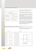
GENERAL REMARKS FOR SETUP The assembly of high voltage circuits using the high voltage construction KIT is quick and easy. An example is the structure of an AC circuit 100 kV (without matching transformer or control unit). Connection Cup Test Transformer Measuring Capacitor Floor Pedestal The configuration is built up by inserting elements to form a self-supporting arrangement. No additional tools are required. Thanks of this simple, but sophisticated design the user can make changes in the circuit quickly and efficiently. That’s especialy an advantage, for combined systems. Every...
Open the catalog to page 4
Compensating Reactor Regulating Transformer Control Unit Digital Measuring Instrument High Voltage Connection High Voltage Connection Smoothing Capacitor Load Capacitor Charging Resistor Wave Front Resistor Wave Tail Resistor Measuring Capacitor Measuring Resistor Grounding Switch Insulating Support Floor Pedestal Secondary Part for CB (Impulse) Coaxial Measuring Cable Triggering Device Electronic Trigger Sphere, incl. cable For AC voltage test system with more than 1 stage compensating reactors are highly recommended. STL 5 (5 kVA) is standard. For test objects with higher capacitive load...
Open the catalog to page 5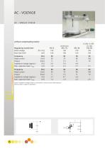
without compensating reactor Regulating transformer Rated voltage Base load (CM) Frequency Rated current Output Impedance voltage (approx.) Max. capacitive load, Cload Frequency Rated current Output Impedance voltage (approx.) Max. capacitive load, Cload remark: Impedance voltage relates to rated power continuous and rated frequency. Technical data is subject to alterations.
Open the catalog to page 6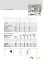
without compensating reactor Impedance voltage (approx.) [%] 4 7 8 Max. capacitive load, C,oad [pF] 180 420 550 Impedance voltage (approx.) [%] 5 8 10 Max. capacitive load, C,oad [pF] 150 320 420 with compensating reactor Regulating transformer Max. capacitive load, C|oad [nF] Max. capacitive load, Cload [nF]
Open the catalog to page 7
without compensating reactor Regulating transformer Impedance voltage (approx.) [%] Max. capacitive load, C|oad [pF] Impedance voltage (approx.) [%] Max. capacitive load, C!oad [pF] | with compensating reactor Regulating transformer Max. capacitive load, C|oad [pF] Max. capacitive load, C|oad [nF]
Open the catalog to page 8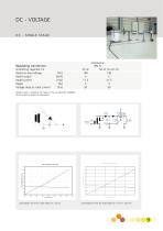
Rated no-load voltage [kV] 140 140 Voltage drop at rated current [kV] 20 30 Rated current is limited by the ripple of 3% according IEC 600060-1. Technical data is subject to alterations Load diagram for KIT DC single stage (CS = 25 nF) Load diagram for KIT DC single stage (CS = 50 nF = 2x25 nF)
Open the catalog to page 9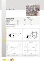
Rated no-load voltage [kV] 280 280 Voltage drop at rated current [kV] 40 60 Rated current is limited by the ripple of 3% according IEC 600060-1. Technical data is subject to alterations Load diagram for KIT DC two stages (CS = 25 nF) Load diagram for KIT DC two stages (CS = 50 nF = 2x25 nF)
Open the catalog to page 10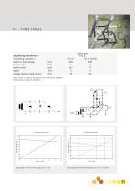
Regulating transformer Rated no-load voltage [kV] Voltage drop at rated current [kV] Rated current is limited by the ripple of 3% according IEC 600060- Technical data is subject to alterations Load diagram for KIT DC three stages (CS = 25 nF) Load diagram for KIT DC three stages (CS = 50 nF = 2x25nF)
Open the catalog to page 11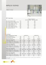
IMPULSE VOLTAGE SINGLE STAGE Max. total charging voltage [kV] Max. energy at max. charging voltage [J] Max. output voltage LI no load [kV] Max. output voltage LI max. load [kV] Max. output voltage SI no load [kV] Max. output voltage SI max. load [kV] Impulse Capacitance Load Range Basic configuration per stage: LI (IEC 60-1) Load capacitor, CB (divider) [nF] 1.2 1.2 Wave tail resistor, RE [k ] 2.4 2.4//2.4 Wave front resistor RDA [ ] 355 355 Load range with RDA, cload [pF] 0...400 0...400 Output voltage at min. load with RDA [kV] 125 130 Output voltage at max. load with RDA [kV] 122 127...
Open the catalog to page 12
Load range for lightning impulse single stage (CS = 25 nF) Load range for lightning impulse single stage (CS = 50 nF = 2x25 nF) Load range for switching impulse single stage (CS = 25 nF) Load range for switching impulse single stage (CS = 50 nF = 2x25 nF)
Open the catalog to page 13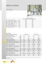
MPULSE VOLTAGE Max. total charging voltage [kV] Max. energy at max. charging voltage [J] Max. output voltage LI no load [kV] Max. output voltage LI max. load [kV] Max. output voltage SI no load [kV] Max. output voltage SI max. load [kV] Impulse Capacitance Load Range Basic configuration per stage: LI (IEC 60-1) Load capacitor, CB (divider) [nF] 1.2 1.2 Wave tail resistor, RE [k ] 2.4 2.4//2.4 Wave front resistor RDA [ ] 355 355 Load range with RDA, C,oad [pF] 0...200 0...200 Output voltage at min. load with RDA [kV] 249 258 Output voltage at max. load with RDA [kV] 243 255 Wave front...
Open the catalog to page 14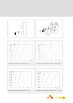
Load range for lightning impulse two stages (CS = 25 nF) Load range for lightning impulse two stages (CS = 50 nF = 2x25 nF) Load range for switching impulse two stages (CS = 25 nF) Load range for switching impulse two stages (CS = 50 nF = 2x25 nF)
Open the catalog to page 15
IMPULSE VOLTAGE THREE STAGES Max. total charging voltage [kV] Max. energy at max. charging voltage [J] Max. output voltage LI no load [kV] Max. output voltage LI max. load [kV] Max. output voltage SI no load [kV] Max. output voltage SI max. load [kV] Impulse Capacitance Load Range Basic configuration per stage: LI (IEC 60-1) SI (IEC 60-1) Load capacitor, CB (divider) [nF] 1.2 1.2 1.2 1.2 Wave tail resistor, RE [k] 2.4 2.47/2.4 120 120//120 Wave front resistor RDA [W] 355 355 55000 55000 Load range with RDA, C,oad [pF] 0...130 0...130 0...100 0...100 Output voltage at min. load with RDA [kV]...
Open the catalog to page 16All Haefely AG catalogs and technical brochures
-
DDX 9160/9161
11 Pages
-
VITAS 2772
4 Pages
-
CITAS 2771
4 Pages
-
2763 / 2767 / 2769
6 Pages
-
AXOS
7 Pages
-
PGR
4 Pages
-
CTTS Series
8 Pages
-
KIT 4.0
10 Pages
-
PSURGE 30.2
4 Pages
-
MAG 1000
8 Pages
-
MIDAS micro 2883
6 Pages
-
TTR 2796
5 Pages
-
PCI 811c
4 Pages
-
ACS
7 Pages
-
2903
4 Pages
-
3695
3 Pages
-
NK SERIES, 3370
4 Pages
-
2767
4 Pages
-
UHVDC - Applied DC Testing
4 Pages
-
DEC 5
2 Pages
-
5478
2 Pages
-
5289
1 Pages
-
5288A
1 Pages
-
5250
2 Pages
-
4762 Range Extender
1 Pages
-
3320 2 kV
2 Pages
-
2914 Solid Test Cell
3 Pages
-
2903 Oil Test Cell
2 Pages
-
2840
4 Pages
-
2830/2831
4 Pages
-
2820a
4 Pages
-
260 DC
2 Pages
-
2293
4 Pages
-
2226a
2 Pages
-
TSS
20 Pages
-
CTT & WPU
8 Pages
-
SSGA 100-150
24 Pages
-
USG 40
2 Pages
-
RM 430
2 Pages
-
PSK
20 Pages
-
R 500 REF, RCZ 500 REF
2 Pages
-
RIC 422
4 Pages
-
RSG 482
3 Pages
-
DMI 551
2 Pages
-
DiAS® 733
6 Pages
-
HiAS® 743
7 Pages
-
KFS
2 Pages
-
MAFS
2 Pages
-
GC 257
6 Pages
-
GC 223
4 Pages
-
SH-H, SH-Q, SH-R
2 Pages
-
DTTS
8 Pages
-
Global Services
8 Pages
-
RSKF
4 Pages
-
Partial Discharge
24 Pages
-
Portable Instruments
13 Pages
-
Product Overview Tettex
20 Pages
-
ONYX ESD simulator
8 Pages
-
Product Overview 2013
24 Pages
-
AXOS 8
20 Pages


