- Catalogs
- Haefely AG
- 2292 Winding Resistance Meter
2292 Winding Resistance Meter
1 /8Pages

2292 Winding Resistance Meter
1 /8Pages
Catalog excerpts
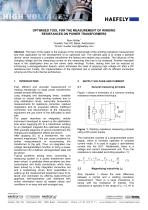
OPTIMISED TOOL FOR THE MEASUREMENT OF WINDING RESISTANCES ON POWER TRANSFORMERS 1Haefely Test AG, Basel, Switzerland *Email: [email protected] Abstract: The topic of this paper is the analysis of the fundamentals of the winding resistance measurement and their application for the development of an optimized tool. The ultimate goal is to create a portable device, which measures a complete transformer the fastest and easiest way possible. The influence of the charging voltage and the measuring current on the measuring time has to be analyzed. Another important issue is the stabilization time on low ohmic delta windings. Further, testing time can be reduced by introducing a demagnetization feature, which eliminates the need of applying high voltage AC after a DC resistance test. Finally, the implementation of the optimized tool is presented with its efficient connection scheme and the multi-channel architecture. Fast, efficient and accurate measurement of winding resistances on large power transformers creates several difficulties. Long charging and discharging times, unstable values on closed delta winding systems due to long stabilization times, inaccurate temperature measurements for resistance correction, residual magnetism and its unwanted effects, inefficient connection and disconnection of the measuring equipment are just some of the difficulties to deal The paper describes an integrated, mobile instrument developed to speed up the stabilisation time when supplying DC to a transformer winding by an intelligent magnetic-flux optimised charging. With example diagrams of various transformers the charging and stabilisation effects are shown. After applying DC to a transformer, the core remains magnetized. This can cause problems for further measurements or reconnecting the transformer to the grid. Thus, an integrated, low voltage demagnetization function to bring a power transformer into a defined, demagnetised state will Typical problems arising when connecting a measuring system to a power transformer have been solved. In particular these problems are time consumption and faulty connections, which have been solved by a fully integrated connection set and a multiplexing circuit. Error possibilities in setting up the measurement equipment have to be faced and eliminated by offering state-of-the-art graphical, self-explanatory user interfaces with online information about all related values and conditions in an easy and well-arranged way. 2 SUPPLY VOLTAGE AND CURRENT 2.1 General measuring principle Figure 1 shows a schematic of a common winding resistance measurement technique. Figure 1: Winding resistance measuring principle using a DC power supply The instrument consists of a programmable power supply, which is normally operated in constant current mode. It is used to supply a user-defined current into the DUT. Additionally, there is a voltage and current measurement unit. Thus, the resistance is calculated according equation (1): Also, Equation 1 shows the main difference between a normal and a winding resistance measurement. There is a large inductance in series with the resistance of interest. This inductance is typically in the range of L0 = 0.1 H to Haefely brands HAEFELYJ&S ILUJUMM HAEFELYJ^W? HIGH VOLTAGE TEST | » & j ft J M E H T J TCCHHQLCHJV WWW Haefely Test AG ■ Birsstrasse 300 ■ 4052 Basel ■ Switzerland ■ Phone +41 61 373 41 11 ■ www.haefely.com ■ www.haefelyemc.com Haefely is a subsidiary High ifoliaga of Hubbell Incorporated, ---Test Business
Open the catalog to page 1
5000H. In figure 2, the current dependency of the magnetizing inductivity is depicted. Figure 2: Inductance of a transformer core By rule of thumb the saturation current can be expressed in terms of the no load current l0: Because of the large magnetizing inductivity of the transformer, the measuring current can not be applied instantaneously. The current can only change according to equation (3): For a given transformer, the rate of change of the measuring current depends only on the voltage applied to the magnetizing inductivity LM. Current charging and discharging time depends mainly on the...
Open the catalog to page 2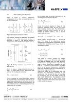
Delta winding considerations Figure 5 shows a common transformer configuration with a delta connected winding on the low voltage side. A Figure 5: Example transformer YNd11 The common method for measuring the winding resistance of a delta connected winding is illustrated in figure 6. The example shows a measurement at the transformer terminals ‘a’ to ‘b’. But in steady state the current distribution will be according equation 6 (for Ra≈Rb≈Rc): Using the method depicted in figure 6, the measured resistance value will only be correct when reaching steady state. By introducing a virtually circulating...
Open the catalog to page 3
FLUX OPTIMIZED YN-DELTA METHOD Experimental Results This section describes another method to decrease the stabilization time on a low ohmic delta winding. The goal of this method is to reduce the magnetizing inductivity by saturating the core, too. But this method uses the high voltage winding to saturate the core, because the saturation current on the high voltage side can be significantly lower than on the low voltage side (depending on the turns ratio): Figure 7 shows the relative steady state flux distribution in the transformer core, when applying a current l2 from 'a' to 'b' on the transformer...
Open the catalog to page 4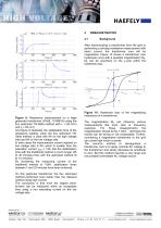
Figure 9: Resistance measurement on a large generator transformer (YNd5, 1100MVA) using the flux optimized YN-Delta method with h = 8A (HV) And figure 9 illustrates the stabilization time of the resistance reading, when the flux optimized YN- Delta method is used with 8A on the high voltage side and 8A on the low voltage side. In both cases the measurement current injected on low voltage side is 8A, which is smaller than the saturation current lSat2 ~ 12A. But the stabilization time with the traditional method is much longer (25 to 30 minutes) than with the optimized method (6 By increasing the...
Open the catalog to page 5All Haefely AG catalogs and technical brochures
 DDX 9160/9161
11 Pages
 VITAS 2772
4 Pages
 CITAS 2771
4 Pages
 2763 / 2767 / 2769
6 Pages
 AXOS
AXOS7 Pages
 PGR
PGR4 Pages
 CTTS Series
8 Pages
 KIT 4.0
10 Pages
 PSURGE 30.2
4 Pages
 MAG 1000
8 Pages
 MIDAS micro 2883
6 Pages
 TTR 2796
5 Pages
 PCI 811c
4 Pages
 ACS
ACS7 Pages
 2903
29034 Pages
 3695
36953 Pages
 NK SERIES, 3370
4 Pages
 2767
27674 Pages
 High Voltage Construction KIT
28 Pages
 UHVDC - Applied DC Testing
4 Pages
 DEC 5
DEC 52 Pages
 5478
54782 Pages
 5289
52891 Page
 5288A
5288A1 Page
 5250
52502 Pages
 4762 Range Extender
1 Page
 3320 2 kV
2 Pages
 2914 Solid Test Cell
3 Pages
 2903 Oil Test Cell
2 Pages
 2840
28404 Pages
 2830/2831
4 Pages
 2820a
2820a4 Pages
 260 DC
2 Pages
 2293
22934 Pages
 2226a
2226a2 Pages
 TSS
TSS20 Pages
 CTT & WPU
8 Pages
 SSGA 100-150
24 Pages
 USG 40
2 Pages
 RM 430
2 Pages
 PSK
PSK20 Pages
 R 500 REF, RCZ 500 REF
2 Pages
 RIC 422
4 Pages
 RSG 482
3 Pages
 DMI 551
2 Pages
 DiAS® 733
6 Pages
 HiAS® 743
7 Pages
 KFS
KFS2 Pages
 MAFS
MAFS2 Pages
 GC 257
6 Pages
 GC 223
4 Pages
 SH-H, SH-Q, SH-R
2 Pages
 DTTS
DTTS8 Pages
 Global Services
8 Pages
 RSKF
RSKF4 Pages
 Partial Discharge
24 Pages
 Portable Instruments
13 Pages
 Product Overview Tettex
20 Pages
 ONYX ESD simulator
8 Pages
 Product Overview 2013
24 Pages
 AXOS 8
20 Pages


- AMOT calibrator
- AMOT capacitor
- AMOT automatic tester
- AMOT industrial tester
- Automatic test kit
- AMOT voltage tester
- Test set
- AMOT industrial testing device
- AMOT ceramic capacitor
- AMOT resistance tester
- AMOT compact tester
- AMOT electrical installation tester
- Immersed transformer
- Indoor service transformer
- AMOT multifunction tester
- AMOT voltage capacitor