- Catalogs
- HACH LANGE
- 2200 PCX Particle Counter Instrument Manual
2200 PCX Particle Counter Instrument Manual

2200 PCX Particle Counter Instrument Manual
The 2200 PCX Particle Counter is enclosed in a NEMA 4X casing, compatible with ¼-inch O.D tubing, and operates on 115 VAC or optionally 220 VAC. It has a flow rate of 100 mL/minute and measures particles from 2 to 750 microns. It meets safety and emissions standards such as UL/CSA, EN 50081-2, and FCC Part 15. Accessories include flow control devices, data collection software, and an OPC server for SCADA systems.
The manual emphasizes safety, highlighting danger, warning, and caution statements. The 2200 PCX features a Class 1 LASER sensor for drinking water applications, supporting local and networked particle count displays and integration with other measurement devices.
Mechanical installation involves mounting and plumbing guidelines, while electrical installation covers wiring safety and ESD considerations. Detailed instructions for RS485 and analog I/O card wiring are provided.
Configuration options include RS485, RS232, and analog I/O settings. The manual explains the 4-20 mA output signal, PC communication protocols, and command syntax.
Regular cleaning is advised, with procedures for brush and stain cleaning. Instructions for long-term storage, sensor flow cell replacement, and tubing replacement are included.
A list of replacement parts and accessories is provided to maintain and expand systems.
Contact details for support and information on the limited warranty by HACH Company are included.
Detailed instructions for configuring the Model 2200 PCX Instrument focus on RS485 and RS232 configurations, using terminal emulation software for communication ports setup.
Steps for configuring RS485 and RS232 include using terminal emulation software, connecting plumbing and cabling, and setting operating parameters.
Setup for analog inputs and outputs involves using jumpers for voltage settings and configuring channels for particle count data.
The output signal is divided into 4,096 steps, with 4 mA representing zero particles/mL and 20 mA representing the full scale value.
Procedures for verifying analog current scaling involve toggling between 4 mA and 20 mA outputs and using an ammeter.
The document outlines communication capabilities and maintenance procedures, with RS232 and RS485 options and ASCII command syntax.
Maintenance tasks include cleaning with chemical solutions, handling with care, and replacing the sensor flow cell and tubing as needed.
Lists of replacement parts and accessories are provided, with item numbers for easy reference.
Contact details for HACH Company and service centers worldwide are included.
A one-year warranty covers defects due to faulty materials or workmanship, excluding consumables and damage from misuse.
Includes tables for setting analog output channels and calculating differential values from cumulative values.
Catalog excerpts

HACH Company, 2008. All rights reserved. Printed in the U.S.A.jk/kt >
Open the catalog to page 1
General EnclosureNEMA 4XFittingsQuick-connect. Connect to -inch O.D tubingPower Requirements115 VAC (ܱ10%); optional 220 VAC (10%); 50/60 HzMaximum Solution Pressure65 psig, not more than 1 minute duration; 55 psig continuousFlow rate100 mL/minute nominalOperating Temperature0і50 C (32Ж122 F)Particle sizeSmallest size: 2 micronsLargest size: 750 micronsIndicatorsPower, counting display, clean sensor and alarmDistance from computer to sensor4000 ft. maximum, entire RS485 signal pathCertificationProduct safety: UL/CSA approved 100Ж115 V, 50/60 Hz external wall-style power supplyImmunity: EN 50081-2:...
Open the catalog to page 5
The contents of this manual is thought to be accurate. The manufacturer is not liable for direct, indirect, special, incidental or consequential damages resulting from any defect or omission in this manual, even if advised of the possibility of such damages. In the interest of continued product development, the manufacturer reserves the right to make improvements in this manual and the products it describes at any time, without notice or obligation. Revised editions are found on the manufacturers web site. > Please read this entire manual before unpacking, setting up or operating this equipment....
Open the catalog to page 7
This symbol indicates a laser device is used in the equipment.This symbol indicated the presence of devices sensitive to Electro-static Discharge (ESD) and indicated that care must be taken to prevent damage with the equipment. safety-fuse.epsThis symbol indicates that the instrument contains a Class 1 LASER device. This product contains a laser-based sensor that is a Class 1 product (as defined by 21 CFR, Subchapter J, of the Health and Safety Act of 1968) when used under normal operation and maintenance. Service procedures on the sensor can result in exposure to invisible radiation. Service...
Open the catalog to page 8
PowerAlarmCountingClean Sensor PowerAlarm CountingClean Sensor Particle Counter Particle Counter Hachs laser-diode-based particle counting sensors are specifically designed for drinking water applications. Water is directed into the sensor and passes through an optical flow cell measuring 750 x 750 microns. Each particle that passes through the sensor generates a signal corresponding to its size. Each sensor comes with a calibration curve showing the signal response versus size of each particle. Hach uses NIST-traceable spheres of defined size to calibrate each sensor. Calibration information...
Open the catalog to page 9
1 2200 PCX sensor (Location 0Ӕ = influent) 5 System computer with data collection software 2 2200 PCX sensor (Location 1Ӕ) 6 Computer cable, standard 25-pin or 9-pin serial > 1 3 2200 PCX sensor (Location 2Ӕ) 7 Converter, RS485 to RS232 4 RS485 cabletotal distance 4000 feet without repeater 8 RS485 communication cable (Beldon 9841 or equivalent) > 1 Or plug converter directly into computer. >
Open the catalog to page 11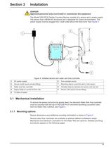
1 AC power supply 6 From sample source 2 Sensor outlet (quick-connect fitting) 7 Mounting clips to mount the weir to the sensor 3 Water weir flow controller 8 Variable distance between the sensor and the weir 4 Adjust height to control the flow rate 9 Sensor inlet (quick-connect fitting) 5 To drain or waste >
Open the catalog to page 13
1 AC power supply 2 Water weir flow controller >
Open the catalog to page 14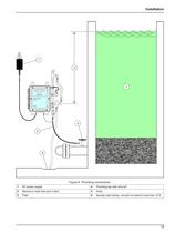
1 AC power supply 4 Plumbing tap with shut-off 2 Maximum head loss plus 4 feet 5 Drain 3 Filter 6 Sample inlet tubingshould not extend more than 10 ft >
Open the catalog to page 15
The most important part of connecting the plumbing is tapping the best sampling location in the water system. A good sampling location ensures a meaningful measurement. Listed below are guidelines for tapping the best location. Refer also to Figure7. Minimize the distance from the tap to the sensor. Օ Tap in a location that can supply 300500 mL/min. flow with four feet of head above the elevation of the sensor. ֕ Tap upstream of a pressure reduction valve or a point where the plumbing becomes larger. These locations tend to create bubbles that can be erroneously counted as particles. Tap 18 inches...
Open the catalog to page 16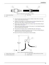
1 Quick-connect fitting 3 Black tubing 2 Nut 4. Route the black semi-rigid tubing (already installed in Water Weir) to the water source; connect tubing to the source. 5. Install an 18 inch piece of -in. flexible tubing (provided with Water Weir) in the Water Weir outlet. Attach to fitting as shown in Figure8. 6. Attach quick-connect fitting to other end of tubing in step 5 then fasten tubing to sensor inlet port. See Figure11. 7. Attach quick-connect fitting to another 12-inch piece of ܼ-inch flexible tubing then insert into particle sensor outlet port. 8. Place other end of tubing in step 7...
Open the catalog to page 17
Note: The more accurately you set the flow, the more accurate the resulting count concentration data. > 1 2200 PCX particle counter 4 Set to 832 mm (33 in.) for approximate 100 mL/min flow 2 Sensor outlet 5 Adjustment capslide up or down to adjust the flow rate > 1 3 Water weir flow controller 6 To drain > 1 To measure the flow rate, rotate the cap and collect sample in a graduated cylinder for 1 minute. To adjust the flow rate by 1ז2mL/min, slide the cap up or down by 1inch. >
Open the catalog to page 18
4. Allow the water to flow through the system for 24 hours before recording measurements. New plastic tubing can shedӔ particles for the first several hours of use. These particles could affect the accuracy of the particle count readings. > 1 Cut the end of the outlet tube straight across 2 Extend the tube no more than inch inside the cap DANGERAlways remove power to the instrument before an electrical connection is made. When making any wiring connection to the instrument, obey the warnings and notes that follow. Obey all warnings and notes in the installation sections. For more safety information...
Open the catalog to page 19
Complete the following steps before connecting wires to the terminal blocks. 1. Press the tabs on the sides of the terminal block to open the block. 2. Properly prepare each wire by removing the insulation on the wires by inch (Figure12). > 12 1 Strip ܼ-inch of insulation. 2 Seat insulation against connector with no bare wire exposed. DANGERElectrocution hazard. Proper fusing and power interruption means must be provided on site. If AC power is wired in conduit, provide a local disconnect next to the instrument. The sensor is pre-wired for power. Plug the AC power supply into an electrical outlet...
Open the catalog to page 20All HACH LANGE catalogs and technical brochures


Archived catalogs
 HQd Insert
2 Pages
 MeterLab Instruments
8 Pages
 VoltaLab Catalog
36 Pages
 TitraLab catalogue
20 Pages
 Electrode Catalogue
20 Pages
 HACH LANGE CATALOGUE 2006/2007
150 Pages


- Measuring device
- Gas analyzer
- Concentration analyzer
- Monitoring analyzer
- Liquids analyzer
- Automatic analyser
- Benchtop analyser
- Solids analyser
- Portable tester
- Process analyzer
- Portable analyzer
- Continuous analyzer
- Digital tester
- Water analyzer
- Real-time analyzer
- Integration analyzer
- Laboratory analyzer
- Oxygen analyzer
- Industrial tester
- Digital gauge