
- Catalogs
- H&b Sensors
- Isolators SEM1000

Isolators SEM1000

Isolators SEM1000
- Input Type: Current input, 2-wire loop powered.
- Range: 4 to 20 mA, with a maximum of 30 mA.
- Protection: Reverse connection protection.
- Voltage Drop: Typically 5.0 V, maximum 5.5 V plus output load.
- Maximum Loop Supply: 35 Volts.
- Output Type: 4 to 20 mA source, powered from input.
- Load: 0 to 300 Ω, with open circuit limits at approximately 15 V.
- Connection: Captive clamp screws, supporting cable sizes up to 4 mm² solid or 2.5 mm² stranded.
- Case Material: Grey Polyamide, flammability rated to UL94-VO VDE 0304 Part 3, Level IIIA.
- Dimensions: 60 x 60 x 12.5 mm, 67.5 mm above rail.
- Mounting: Snap on "top hat" rail (DIN EN 50022-35).
- Isolation: 500 V DC, flash tested at 1 kV, using opto coupler/transformer method.
- Electrical Safety: Complies with BS EN61010-1, Pollution Degree 2, Installation Category II, Class I.
- Ambient Conditions: 0 to 70 ºC, 10 to 95% RH non-condensing.
- Accuracy: 0.05% full range output.
- Stability: 0.01% per ºC.
- Response Time: Less than 100 ms to reach 63% of final value.
- EMC: Tested to BS EN 61326.
- Adjustments: Zero and Span Adjustment available.
Catalog excerpts

SEM1000 Loop Splitter 1 Channel process signal isolator 4 to 20mA Output The SEM1000 isolator is designed to be series connected into a new or existing 4 to 20 mA current loop and provide an isolated 4 to 20 mA signal capable of driving into a 300 Ω load. The output is powered from the input loop. Minor adjustments can be made to the calibration of the device by means of the two front panel accessible calibration potentiometers. Specification Input Type Range Protection Voltage Drop Maximum Loop Supply ISOLATION EXISTING LOOP Current input 2 wire Loop powered 4 to 20 mA (30 mA MAX) Reverse connection 5.0 V typical, 5.5 V Maximum (Plus output load) 5.5 + (load * 0.02) 35 Volts Output Type Load 4 to 20 mA source (Powered from input) 0 to 300 Ω (Open circuit limits at approximately 15 V) Connection Cable Size Case Material Flammability Dimensions Mounting Captive clamp screws Maximum 4 mm sq solid / 2.5 mm sq stranded Grey Polyamide To UL94-VO VDE 0304 Part 3, Level IIIA 60 x 60 x 12.5 mm (67.5 above rail) Snap on “top hat” rail (DIN EN 50022-35) Isolation 500 V DC (flash tested @ 1 kV) (Isolation method, opto coupler / transformer) Electrical Safety BS EN61010-1 POLLUTION DEGREE 2; INSTALLATION CAT II ; CLASS I Ambient 0 to 70 ºC ; 10 to 95 % RH non condensing Accuracy 0.05 % full range output Stability 0.01 % / ºC Response Time Less than 100 mS to reach 63 % of final value. EMC Tested to BS EN 61326 Adjustments Zero and Span Adjustment H&B Sensors Ltd | Odyssey House | Durban Road | Bognor Regis | West Sussex | PO22 9RH | United Kingdom Tel: +44(0)1243 866866 | Email: [email protected] | www.hbsensors.com
Open the catalog to page 1All H&b Sensors catalogs and technical brochures
 Process Controllers P1611100
2 Pages
 Isomators SEM1200
1 Page
 Junction Boxes Type 40
1 Page
 Isolators MTL 5541
1 Page
 Indicators PAXT0000
2 Pages
 Indicators BA307E
2 Pages
 Indicators HBS16001
1 Page
 Connection Heads Type 48
1 Page
 Connection Heads Type 44
1 Page
 Connection Heads Type 38
1 Page
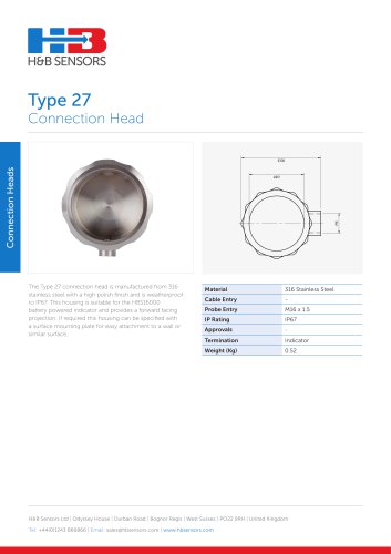 Connection Heads Type 27
1 Page
 Connection Heads Type 15
1 Page
 Connection Heads Type 8
1 Page
 Connection Heads Type 2
1 Page
 Bimetallic A
2 Pages
 5333A
5333A2 Pages
 PAXP0000
2 Pages
 Process Controller T1611100
3 Pages
 Miniature Heaters
2 Pages
 HBS16000
1 Page


- Temperature probe
- Resistance temperature sensor
- Digital indicator
- Panel panel meter
- Thermocouple temperature transducer
- Level transmitter
- Liquid level transmitter
- RTD temperature sensor
- Liquids level gauge
- Temperature transmitter
- Insertion temperature sensor
- RTD temperature transmitter
- Temperature indicator
- Storage tank level transmitter
- Sight glass level indicator
- Air temperature probe
- Process temperature transmitter
- Explosion-proof level transmitter
- Current output temperature transmitter
- Pt100 temperature transmitter