
Catalog excerpts

DELIVERING THE FUTURE OF COMPOSITE SOLUTIONS
Open the catalog to page 1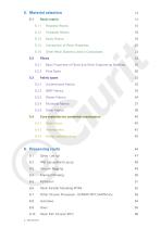
5.1.5 Other Resin Systems used in Composites 23 5.2.1 Basic Properties of Fibres and Other Engineering Materials 25 5.4 Core materials for sandwich construction 40 6.6 Resin Transfer Moulding (RTM) 52 6.7 Other Infusion Processes - SCRIMP, RIFT, VARTM etc. 53 6.10 Resin Film Infusion (RFI) 56
Open the catalog to page 4
72 Pre -treatment prior to bonding 59 73.6 Heat stable adhesives: Bismaleimides, polyimides, cyanate esters 61
Open the catalog to page 5
Guide to Structural Composites Introduction To fully appreciate the role and application of composite materials to a structure, an understanding is required of the component materials themselves and of the ways in which they can be processed. This guide looks at basic composite theory, properties of materials used and then the various processing techniques commonly found for the conversion of materials into finished structures. 1.1 Basic Composite Theory In its most basic form a composite material is one, which is composed of at least two elements working together to produce material...
Open the catalog to page 6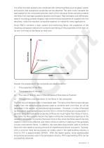
It is when the resin systems are combined with reinforcing fibres such as glass, carbon and aramid, that exceptional properties can be obtained. The resin matrix spreads the load applied to the composite between each of the individual fibres and also protects the fibres from damage caused by abrasion and impact. High strengths and stiffnesses, ease of moulding complex shapes, high environmental resistance all coupled with low densities, make the resultant composite superior to metals for many applications. Since PMC’s combine a resin system and reinforcing fibres, the properties of the...
Open the catalog to page 7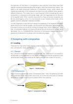
The geometry of the fibres in a composite is also important since fibres have their highest mechanical properties along their lengths, rather than across their widths. This leads to the highly anisotropic properties of composites, where, unlike metals, the mechanical properties of the composite are likely to be very different when tested in different directions. This means that it is very important when considering the use of composites to understand at the design stage, both the magnitude and the direction of the applied loads. When correctly accounted for, these anisotropic properties can...
Open the catalog to page 8
2.1.3 Shear Figure 3 shows a composite experiencing a shear load. This load is trying to slide adjacent layers of fibres over each other. Under shear loads the resin plays the major role, transferring the stresses across the composite. For the composite to perform well under shear loads the resin element must not only exhibit good mechanical properties but must also have high adhesion to the reinforcement fibre. The interlaminar shear strength (ILSS) of a composite is often used to indicate this property in a multi-layer composite (‘laminate’). Figure 3 – Shear loading 2.1.4 Flexure...
Open the catalog to page 9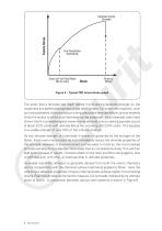
Figure 5 – Typical FRP stress/strain graph The strain that a laminate can reach before microcracking depends strongly on the toughness and adhesive properties of the resin system. For brittle resin systems, such as most polyesters, this point occurs a long way before laminate failure, and so severely limits the strains to which such laminates can be subjected. As an example, tests have shown that for a polyester/glass woven roving laminate, micro-cracking typically occurs at about 0.2% strain with ultimate failure not occurring until 2.0% strain. This equates to a usable strength of only...
Open the catalog to page 10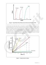
Figure 6 - Typical Resin Stress/Strain Curves (Post-Cured for 5 hrs @ 80°C It should also be noted that when a composite is loaded in tension, for the full mechanical properties of the fibre component to be achieved, the resin must be able to deform to at least the same extent as the fibre. Figure 7 gives the strain to failure for E-glass, S-glass, aramid and high-strength grade carbon fibres on their own (i.e. not in a composite form). Here it can be seen that, for example, the S-glass fibre, with an elongation to break of 5.3%, will require a resin with an elongation to break of at least...
Open the catalog to page 11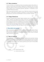
2.3 Fibre orientation It is rare for fibres in a composite laminate to be perfectly aligned. Woven fabrics introduce a crimp to fibres which causes misalignment of load paths. Even non woven fabrics can suffer from some crimping around stitch points. The misalignment of fibres causes dramatic loss of mechanical properties, particularly in compression, due to increased likelihood of buckling. When using unidirectional fabrics, tapes or tows, it becomes critical to ensure accurate alignment of fibres during component manufacture to ensure loads are transferred efficiently and to maximize the...
Open the catalog to page 12
Based on RoM a composite property, Pc, can be estimated by: Pc = Pf Vf + PmVm = Pf Vf + Pm (1-Vf) where Pf & Pm = The property of fibre For example elastic modulus, E1, parallel to fibre direction can be calculated based on the Youngs modulus of each of the constituent materials: E1 =Ef Vf + Em Vm This equation is easily understood by considering the analogy of calculating the stiffness of 2 springs connected in parallel: Unit volume Figure 8 – RoM model for longitudinal properties For the elastic modulus perpendicular to fibre direction the calculation becomes a little more sophisticated,...
Open the catalog to page 13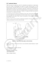
3.2 Laminate theory RoM formulae and models are useful for calculating the properties of single layers but more complex methodologies are required to enable characterisation of multi plied laminates. Laminate Plate Theory (LPT) is a complex but well established and accepted approach. Whilst too complicated to describe in detail here LPT describes the deformation of a laminate under external loading based on the properties of the fibre, matrix and the % of each in each axis of loading. It is logical and easily automated for incorporation into engineering models. It is quite obvious that...
Open the catalog to page 14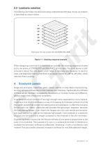
3.3 Laminate notation Considering a laminate manufactured using unidirectional (UD) plies, the lay up notation is described as shown below : Figure 11 – Stacking sequence example When designing a laminate it is important to consider the stacking sequence of plies and to be aware of SYMMETRY and BALANCE of the stack. The stack above is both symmetric (about the mid plane) which helps to eliminate any tendency to bend or warp, and balanced meaning that there is an equal number of +45° & -45° plies, which reduces shear coupling. 4. Sandwich panels Single skin laminates, made from glass,...
Open the catalog to page 15All Gurit catalogs and technical brochures
-
GURIT® G-PET™ FR
4 Pages
-
FST Materials Brochure (v10)
7 Pages
-
PREPREGS
11 Pages
-
EH 275 / EP 114
4 Pages
-
Carbon & Glass SparPreg
5 Pages
-
General Datasheet PN 901
4 Pages
-
General Datasheet PN 900
4 Pages
-
General Datasheet PB1000
4 Pages
-
RA320H5
1 Pages
-
XA450
1 Pages
-
UT-EA661
1 Pages
-
REA390S
1 Pages
-
PB1000
2 Pages
-
Adhesives Brochure (v7)
5 Pages
-
Core Materials Brochure (v8)
9 Pages
-
GURIT PRODUCT CATALOGUE 2013/14
82 Pages
-
UT-E1200
1 Pages
-
UT-E800
1 Pages
-
UT-E500
1 Pages
-
UT-E250
1 Pages
-
Carbon SparPreg (v9)
4 Pages
-
RENUVO Prepreg PP (v4)
3 Pages
-
Gurit Guide to Composites (v5)
73 Pages
Archived catalogs
-
Corecell P-Foam
2 Pages


