
- Catalogs
- GUANGZHOU LINK AUTOMATION EQUIPMENTCO., LTD
- LKR series without cover, LKR series with cover, aluminum, Linear Motion Modules - Single Axis Robot


LKR series without cover, LKR series with cover, aluminum, Linear Motion Modules - Single Axis Robot
LKR series without cover, LKR series with cover, aluminum, Linear Motion Modules - Single Axis Robot
The LKR Series linear module is designed for high-precision industries, integrating a ballscrew and guideway for accuracy, stiffness, and compactness. It is ideal for sectors like photovoltaic, automation, and lithium battery equipment.
Caution and Life Safety
Install away from fire sources and flammable materials. Avoid dropping or modifying the product. Store flat, avoiding extreme temperatures and humidity. Lock during installation to prevent loosening. Follow rated conditions to prevent damage or accidents. Consult the manufacturer for special environmental conditions.
Storage and Installation
Store properly to avoid extreme conditions. Ensure proper alignment and fittings during installation. Replenish grease before first use and maintain regularly.
Operation Use
Operate within rated conditions, avoiding foreign objects in the ball circulation system. Consult the manufacturer for high-temperature or special environments.
Maintenance
Check every 100km, clean dirt, and replenish grease. Ensure alignment and use flexible couplings.
Selection Steps
Consider user requirements, precision demands, configuration, motor selection, and operation analysis. Confirm conditions of use and special requirements.
Precision
Includes positioning accuracy, repeatability, and running parallelism. Ensure maximum linear velocity and rotational speed are within limits.
Motor Loading Calculation
Calculate momentum, acceleration, and deceleration torques. Ensure motor output torque exceeds the sum of acceleration and load torques.
Installation and Service Life
Service life depends on orientation and load conditions. Maintain within listed dynamic load for extended service life.
Features and Applications
High accuracy, stiffness, and easy installation. Suitable for high-precision and automation industries.
Various Specifications and Accessories
Available in different sizes and configurations. Optional accessories include aluminum covers, motor adaptor flanges, and limit switches.
Ordering Information
Details on size, ballscrew lead, accuracy grade, rail length, and block type.
Nominal Life and Calculation
Nominal life predicts service life, calculated using guideway and ballscrew formulas. Key parameters include life rating, basic dynamic load rating, contact coefficient, and loading coefficient.
Lubrication
Proper lubrication extends service life, reduces friction, prevents abrasion, and provides anti-rusting properties. Re-lubrication is recommended every 100 km, especially for speeds under 60 m/min, using high-viscosity grease.
Specifications
Detailed specifications for LKR models (LKR 50, LKR 60, LKR 86) include total length, rail length, maximum stroke, and weight. Information on motor housing and motor adaptor flanges is also provided.
Tables and Data
Tables detail contact and loading coefficients, rail lengths, maximum strokes, and weights for different configurations, essential for understanding specific requirements and limitations of each LKR model.
Catalog excerpts

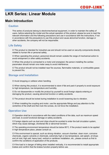
LKR Series: Linear Module Main Introduction Caution This series of products belong to electromechanical equipment, in order to maintain the safety of users, before selecting the model and the actual operation of this product, please be sure to read the relevant information and the following precautions and use in accordance with the instructions, if not in accordance with the precautions to use this product and cause abnormal function, damage or other accidents, the company will not be responsible. Life Safety O This product is intended for industrial use and should not be used on security components directly related to human life or personal safety. O When operating this product, personnel should remain outside the range of mechanical action to avoid entrapment or other safety accidents. O When this product is connected to a motor and energized, the person installing the cardiac pacemaker should remain one meter away to avoid interference. O This product should not be installed near fire sources, flammable materials, or combustible gases to prevent fire. Storage and Installation O Avoid dropping or collision when handling. O When storing this product, it is recommended to store it flat and pack it properly to avoid exposure to high temperature, low temperature and humidity. O Do not disassemble or modify the product by yourself to avoid foreign objects entering or damaging the product, causing abnormal function or safety accidents. O The product should be locked during installation to avoid loosening due to vibration. O When installing the coupling and motor, use the appropriate fittings and pay attention to the centerline of the shaft and then lock the screws, do not force the installation. Operation Use O Operation shall be in accordance with the rated conditions of the data, such as maximum speed and load, to avoid functional damage or safety accidents. O Foreign objects such as dust and chips should be avoided to enter the ball circulation system, which may cause damage, shortened life or abnormal function. O The operating environment temperature should be below 80° If the product needs to be applied C. in high temperature place, please consult us. O If the environment is special, such as strong vibration, vacuum chamber, clean room, corrosive chemicals, organic solvents or chemicals, extremely high or low temperature, wet splash, oil drops and oil mist, high salt, heavy load, vertical or cantilever installation, etc., please consult us first to confirm the conditions of application of the products. O If the load is in danger of falling when installed vertically, it is recommended to install appropriate brakes and confirm that the brakes function properly before use.
Open the catalog to page 1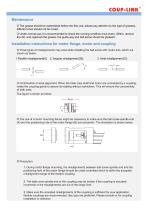
Maintenance O The grease should be replenished before the first use, please pay attention to the type of greases, different ones should not be mixed. O Under normal use, it is recommended to check the running condition once every 100km, remove the dirt, and replenish the grease, the guide way and ball screw should be greased. Installation instructions for motor flange, motor and coupling O Three types of misalignments may exist while installing the ball screw with motor axis, which are shown as below. 1.Parallel misalignment[A]: 2. Angular misalignment [B]: O Confirmation of axial alignment:...
Open the catalog to page 2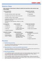
Selection Steps When choosing a module based on different conditions and restrictions, below selection steps may be helpful: 1. User requirements O Location restrictions (width, height, length) O Installation type (horizontal, vertical, side mount) O Position of gravity, center of loading O Operating conditions (lead, speed, acceleration and deceleration, duty cycle) O Environment (high temperature, vibration, oil, water, corrosion) 3. Configuration 5. Motor load calculation O With or without brake (included, plug-in) O Motor torque calculation O Special combination 6. Operation analysis O Acceleration...
Open the catalog to page 3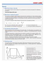
Speed 1. Maximum linear velocity The module's maximum linear velocity (V) is calculated from the ball screw speed (S) multiplied by the lead (L). V(mm/sec)=S(rpm)÷ 60×L(mm) 2. Maximum rotational speed The maximum allowable rotational speed of the ball screw is decided by it's critical rotational speed. If the ball screw speed exceeds it's critical speed it may result in resonance. Hence, the critical speed is related to the ball screw length, the critical speed can help to determine the ball screws effective stroke and total length. The maximum allowable rotational speed of the ball screw is...
Open the catalog to page 4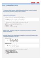
Motor Loading Calculation 1. Confirm the moving conditions required by the loading mechanism, including acceleration, deceleration, the weight of the mechanism and it's movement. 2. Momentum loading calculation: Momentum calculation for loads moving along a straight line JL : Momentum of load, calculated to the motors axial output (kg.cm2) V : Velocity of load along a straight line(mm/min) ΔS : Displacement of load per motor rotation(mm) W : Weight of load (kg) N : Rotational speed of motor[r/min] 3. Select suitable specification of motor with the proportional principle per the momentums between...
Open the catalog to page 5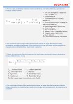
5. Per the loads, installation methods, friction coefficients, and motor efficiency, calculate the torque at uniform motion. F : Axial force moving along a straight line F=FC + μx (Wxg + F0) TL : Load torque (N.m) FC : External force exerted in the axial direction (N) F0 : External positive pressure exerted by the load onto the module (N) W : Load (including sliding platform) (kg) μ : Friction coefficient η : Mechanical efficiency V : Velocity of load in a straight line (mm/min) N : Rotational speed of motor (r/min) g : Gravity (9.8m/s2) ΔS : Displacement of load per motor rotation (mm) 6. The...
Open the catalog to page 6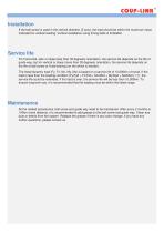
Installation If the ball screw is used in the vertical direction (Z axis), the load should be within the maximum value indicated for vertical loading. Vertical installation using timing belts is forbidden. Service life For horizontal, side or slope (less than 30 degrees) orientation, the service life depends on the life of guide way, but for vertical or slope (more than 30 degrees) orientation, the service life depends on the life of ball screw or fixed bearing (on the which is shorter). The listed dynamic load (Fy, Fz, Mx, My, Mz) is based on a service life of 10,000km of travel. If the load...
Open the catalog to page 7All GUANGZHOU LINK AUTOMATION EQUIPMENTCO., LTD catalogs and technical brochures
 CLKZ series, motor bracket
5 Pages
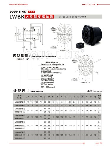 LWBK series
2 Pages
 LK23-C series
7 Pages
 LK31-C series
8 Pages
 LK19 series, rubber coupling
3 Pages
 LK29 series, spring coupling
2 Pages
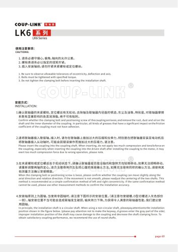
 Jaw coupling, LK30-C series
4 Pages
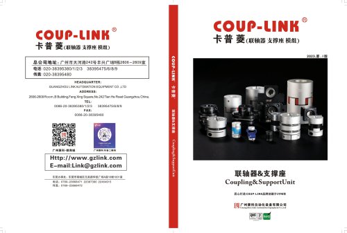 Catalogue of Coup-Link 2023
175 Pages
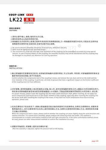
 LK5-C-WP series, double disc
8 Pages
 Product Overview-2019
5 Pages
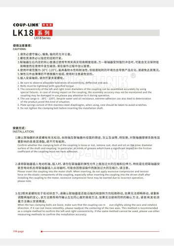
 Jaw coupling, LK8-C series
4 Pages













- Angular encoder
- Incremental encoder
- Incremental rotary encoder
- Shaft shaft coupling
- Solid-shaft rotary encoder
- Industrial rotary encoder
- Hollow-shaft rotary encoder
- Flange coupling
- Metal stand
- Torque coupling
- Compact rotary encoder
- Aluminum rotary encoder
- DC rotary encoder
- Rigid coupling
- Transmission coupling
- Zero-backlash shaft coupling
- Bearing unit
- High-resolution rotary encoder
- Digital rotary encoder