- Catalogs
- Guangzhou Aipu Electron Technology Co.,Ltd
- NN1-XXSXXH6 Series
NN1-XXSXXH6 Series
1 /5Pages

NN1-XXSXXH6 Series
1 /5Pages
Catalog excerpts

DC-DC Converter NN1-XXXXXH6 Series ULNIDN (o era Typical Features ♦ Fixed input voltage, isolated& unregulated output, output power 1W ♦ High efficiency up to 75% ♦ Small compact SIP packing ♦ No external component required ♦ Isolation Voltage 6000VDC ♦ Plastic Case, meet UL94-V0 standard Test Condition: Unless otherwise specified, data in the datasheet should be tested under the conditions of inputting nominal voltage, pure resistance rated load and Ta=25C. Product Named Method - (7)6 means isolation 6KVdc - @19.5*9.8*12.5mm plastic packing - 15 .Output Voltage 5V - ©S:single output; D: dual output - @Nominal input voltage 5V ©Output power 1 W - (l)±10% rated voltage input unregulated output s Input Specifications Item Output Specifications Other input Continuous, Self-recovery Output Short Circuit Protection© Note: ©Ripple & Noise tested by twisted-pair method, ©There is a small portion can only be guaranteed to be within 5 second. http://www.aipulnion.com E-mail: [email protected] TEL: 86-20-84206763 FAX: 86-20-84206762 HOT-LINE: 400-811-8032 Page 1 o
Open the catalog to page 1
Note: 1.“*” are models under developing. 2. In order to ensure the converter can work reliably with high efficiency, the minimum load should not less than 10% rated load when it is used. If the needed power is indeed small, please parallel a resistor at the output side, the resistance recommended equal to 10% nominal power. 3. The capacitive loads of positive and negative outputs are identical. Temperature Derating Curve 100% http://www.aipulnion.com E-mail: [email protected] TEL: 86-20-84206763 FAX: 86-20-84206762 HOT-LINE: 400-811-8032 Page 3 o
Open the catalog to page 3
Front view Packing Dimension Recommended PCB layout
Open the catalog to page 4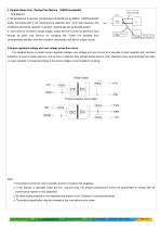
3. Ripple& Noise Test: (Twisted Pair Method Test Method: a.12# twisted pair to connect, Oscilloscope bandwidth set as 20MHz, 100M bandwidth probe, terminated with 0.1uF polypropylene capacitor and 47uF high frequency low resistance electrolytic capacitor in parallel, oscilloscope set as Sample pattern. b. Input terminal connect to power supply, output terminal connect to electronic load through jig plate, Use 30cm± cm sampling line, Power line selected from 2 corresponding diameter wire with insulation according to the flow of output current. 4.Output regulated voltage and over voltage protection...
Open the catalog to page 5All Guangzhou Aipu Electron Technology Co.,Ltd catalogs and technical brochures
 WD50-XXSXXK1 Series
4 Pages
 WD30/40 Series
3 Pages
 WD30-XXXXXD1 Series
6 Pages
 WD25-30D1 Series
3 Pages
 RSH485-XXH Series
4 Pages
 WR30-XXS75 WR40-XXS75 Series
3 Pages
 BK25-600DXXH1 Series
6 Pages
 BK20-600SXXH1 Series
5 Pages
 BK20-600DXXH1 Series
6 Pages
 BK15-600SXXH1 Series
5 Pages
 BK15-600DXXH1 Series
5 Pages
 WD75-XXSXXM1 series
4 Pages
 FD50-XXSXXB3(C) Series
9 Pages
 FD50-110SXXB3(C) Series
9 Pages
 FD40-XXSXXB3C3 Series
9 Pages
 FD30-XXSXXB3(C) Series
9 Pages
 FD30-XXSXXA3(C) Series
9 Pages
 FD30-110SXXB3C3 Series
9 Pages
 FD25-XXSXXB3(C) Series
8 Pages
 WD20-XXXXXC1 Series
6 Pages
 UD6-XXXXXE3 Series
6 Pages
 UD3-XXXXXE23/E3 Series
6 Pages
 FD6-XXSXXA3 Series
8 Pages
 FD6-XXDXXA3 Series
7 Pages
 FD6-110SXXA3(C) Series
6 Pages
 FD20-XXSXXA3(C) Series
8 Pages
 FD20-XXDXXA3(C) Series
8 Pages
 FD15-XXSXXA3(C) Series
7 Pages
 FD15-XXDXXA3(C) Series
10 Pages
 FD12-XXSXXA3(C) Series
8 Pages
 FD12-XXDXXA3(C) Series
8 Pages
 FD12-110SXXA3(C) Series
6 Pages
 FD10-XXSXXA3(C) Series
7 Pages
 FD10-XXDXXA3(C) Series
8 Pages
 NW2-XXSXXC3 Series
3 Pages
 NW1-XXSXXB3 Series
4 Pages
 NN2-XXXXXH6 Series
5 Pages
 KW3-XXXXXEA Series
5 Pages
 KW3-XXXXXE3 Series
8 Pages
 KW2-XXXXXEA Series
6 Pages
 KW2-XXXXXE3 Series
8 Pages
 KW1-XXXXXE3 Series
8 Pages
 WA54-220D18K1 Series
6 Pages
 WA50/60-220XXXK1B Series
4 Pages
 FA40-220SXXH3 Series
6 Pages
 UA15-220H05XXXXF2 Series
6 Pages
 UA12-220SXXD3A Series
5 Pages
 UA10-220SXXP2 Series
6 Pages
 U10-220SXXP2D Series
5 Pages
 FA8-220SXXD2 Series
6 Pages
 FA6-220SXXD3 Series
6 Pages
 FA6-220SXXD2 Series
5 Pages
 FA30-220SXXH2 Series
6 Pages
 FA25-220SXXH2 Series
7 Pages
 FA25-220E05XXH2 Series
6 Pages
 FA20-220H05XXXXH2 Series
6 Pages
 FA15-380S05H24 Series
6 Pages
 FA15-220SXXY2 Series
6 Pages
 FA15-220SXXF2 Series
7 Pages
 CK6-380SXXE2 Series
5 Pages
 WA3-220SXXA3 Series
5 Pages
 FA5-220SXXY2 Series
6 Pages
 FA5-220SXXC2 Series
6 Pages
 FA5-220EXXXXC2 Series
6 Pages
 FA3-220SXXA2A series
6 Pages
 FA2-220SXXA2A Series
6 Pages
 FA1-220SXXN2 Series
5 Pages
 FA5-220SXXB-1 Series
7 Pages
 FA3-220SXXB-1 series
7 Pages
 UA2-220SXXB series
7 Pages
 NA200-220SXXM1 Series
3 Pages
 UA10-220XXXP2 Series
5 Pages
 UA15-XXXXXF2 Series
5 Pages
 UA20-220HXXXXXXH2 Series
6 Pages
 UA15/20-220HXXXXXXF2 Series
5 Pages
 UA20-220XXXF2/F3 Series
6 Pages
 UA25-220XXXH2 Series
6 Pages
 NN2-XXXXXC3N Series
5 Pages
 NN1-XXSXXANT Series
5 Pages
 NN1-XXXXXBN Series
5 Pages
 NN1-XXXXXB3N Series
5 Pages
 NN1-XXSXXAN Series
5 Pages
 KW3-XXXXXE Series
8 Pages
 K78XX-500 Series
4 Pages
 BB40-BB100 Series
4 Pages
 BA150-BA200 Series
4 Pages
 AC25-380S12H2 Series
6 Pages
 FA10-220SXXE2 Series
6 Pages
 FA20-220HXXXXXXH2 Series
6 Pages
 FA3-220SXXA2A
6 Pages
 FA3-220SXXB Series
7 Pages
 K78XX-1000 Series
4 Pages
 WA6-220SXXD3 Series
5 Pages
 WA40/50-220XXXK1 Series
5 Pages
 FA5-220SXXB Series
7 Pages
 AC25-H2 Series
6 Pages


- DC power supply
- AC/DC power supply
- Switching power supply
- DC-DC converter
- Transceiver module
- Industrial DC/DC converter module
- Single-output DC/DC converter module
- Chassis-mounted DC/DC converter module
- SMD DC-DC converter
- Current rectifier
- High-speed transceiver
- Switching DC-DC converter
- DC/DC converter for telecom applications
- Data transmission transceiver
- Non-isolated DC-DC converter
- Compact DC/DC converter module
- High MTBF DC/DC converter
- Encapsulated power supply
- Regulated DC/DC converter