
- Catalogs
- Guangdong Dingshen Electric Technology Co. LTD
- Servo Motor User Manual FT2


- Company
- Products
- Catalogs
- News & Trends
- Exhibitions
Servo Motor User Manual FT2

Servo Motor User Manual FT2
Users must follow safety guidelines during product storage, installation, wiring, operation, inspection, and maintenance to ensure safe usage. Key warnings include:
- Danger: Mishandling can lead to personal injury or death.
- Notice: Mishandling can result in personal injury, death, and equipment damage.
- Prohibit: Certain actions are strictly prohibited to prevent equipment damage or malfunction.
Do not use the product in environments with moisture, corrosive, or flammable gases, direct sunlight, dust, salt, metal powder, dripping water, oil, or chemicals to avoid electric shock or fire.
Ensure reliable grounding and correct connections to prevent electric shock, fire, and equipment damage. Specific instructions include:
- Ground the grounding terminal.
- Do not connect a 220V driver power supply to a 380V power supply.
- Connect U, V, W motor output terminals correctly.
- Secure power supply and motor output terminals.
Adjust mechanical equipment parameters before operation, ensure the emergency switch is functional, test the servo motor without load, and avoid frequent power cycling to prevent overheating.
Avoid touching rotating parts or moving connection cables during operation to prevent injuries or equipment damage.
Do not touch the inside of the driver and motor, remove the driver panel when power is on, or touch terminals within 5 minutes after power off to prevent electric shock.
The products are intended for general industrial use and should not be used in devices that may directly endanger personal safety.
Inspect the product for model accuracy, damage, and loose components upon delivery. Ensure the rotor shaft of the servo motor rotates smoothly and verify the inclusion of the servo operation manual and drive accessories.
Output power ranges from 0.4KW to 1.5KW with single-phase AC220V input. Control methods include position, speed, torque, and hybrid control modes. Protective functions cover overspeed, overvoltage, undervoltage, overcurrent, overload, and encoder abnormalities. Communication methods include RS485 and canopen.
Follow specific wiring instructions to ensure correct power supply connections and prevent malfunctions. Maintain a safe distance between power and signal lines to avoid interference. Install a non-fuse circuit breaker for timely power cut-off during failures.
Wire sizes for various connections in the FT2 Servo system are specified. Main circuit power, motor connection, and ground terminals require wires of 1.5~4mm². Control and encoder signal terminals require wires of at least 0.14mm² (AWG26), including shielded wires. Encoder cables must be twisted pair, and if longer than 20m, thicker wires or multiple cables should be used to prevent power insufficiency.
The document provides a schematic diagram of the FT2 terminal pin distribution, detailing the layout of the terminals delivered with the driver body.
The main circuit power input terminal accepts single-phase 220VAC with a tolerance of -15% to +10%. Brake resistor terminals have specific configurations for internal and external resistors. Motor connection terminals link to the U, V, W phases of the servo motor, and the drive ground terminal connects to both power supply and motor ground terminals.
For internal braking resistors, terminals B and C should be short-circuited. For external resistors, disconnect B and C and connect the resistor across B and D. The document warns against connecting external brake resistance to the positive and negative busbar P and N to avoid explosion and fire.
This terminal provides signals for connecting with the upper controller, including programmable inputs and outputs, analog command input, and command pulse input. The document advises using 24-26 AWG cables.
The document describes the position command input signal, including pulse modes and maximum frequency and pulse width specifications. It warns against exceeding signal levels of 5V without external resistors.
The document details the default functions and configurations for digital input and output signals, including enable, emergency, error clear, and mode switch inputs, as well as enable, alarm, position reached, and speed reached outputs.
The document describes the analog command input for speed/torque, with a range of -10V to +10V and an input impedance of about 10KΩ. Differential input connection is recommended.
The brake mechanism prevents servo motor shaft movement when not running. The document provides a wiring diagram and cautions about the lock mechanism's limitations and potential flux leakage.
The CN2 terminal connects to the motor encoder using a 6PIN socket. The document advises against sharing power with other appliances to prevent voltage or current reduction.
CN3 and CN4 ports facilitate communication between the driver and PC, PLC, and other drivers. The document provides pin definitions and wiring diagrams for RS485 communication.
To suppress interference, the document recommends keeping command input cables under 3m, using thick ground wires, installing noise filters, and separating strong and weak current lines by at least 30cm.
Use a filter on the input side of the power line to prevent interference. PLC includes a built-in 485 communication terminal resistor. Ground the shielding layer at one end only. Avoid connecting the GND terminal of the upper device to the E0V terminal of the servo driver to prevent damage.
Ground the servo motor housing by connecting its ground terminal to the PE terminal of the servo drive. Ground both ends of the motor encoder cable's shielding layer. Use a noise filter at the power input end to reduce interference, ensuring separate wiring for input and output.
- Position Control Mode: Utilizes pulse frequency to control movement and speed, suitable for positioning devices like CNC machines.
- Speed Control Mode: Controls rotation speed through various settings, used in constant speed applications.
- Torque Control Mode: Manages torque through analog and digital settings, ideal for winding devices with strict force requirements.
Position mode requires specific wiring and parameter adjustments for gain, smoothing filters, and electronic gear ratios. Speed mode involves setting proportional gains, integral coefficients, and acceleration/deceleration times. Torque mode requires adjustments for torque limits and control compensation points.
Ensure no damage to the servo drive and that all wiring is insulated and correctly connected. Verify that the servo motor can operate without load before connecting it to avoid danger.
The drive panel includes LED displays and buttons for setting parameters and displaying system states. Parameters are set through a hierarchical menu system, with modifications saved immediately or upon power cycling.
This document is a technical manual for the FT2 Servo system, detailing its operation, display interface, and parameter functions. It includes instructions for monitoring, jog operations, restoring default parameters, and a comprehensive description of parameter functions.
The system offers 14 display states, selectable via specific keys. Key parameters include feedback speed, position commands, motor torque, and system error codes, each with a unique Modbus address and data type.
To perform jog operations, the motor must be connected to the driver, which automatically reads and matches motor parameters. Users can adjust parameters to enter JOG mode and save settings by holding the SET key.
This function is used when parameters are incorrect, causing system malfunction. The process involves entering parameter management, selecting the appropriate mode, and saving the default settings.
The document provides detailed descriptions of various parameters, including:
- PR Group Parameters: These include password protection, software and hardware versions, motor model specifications, and control mode selection.
- Control Modes: Various control modes are available, such as position control, speed control, torque control, and Modbus control, each with specific settings and applications.
- Speed and Position Gains: Parameters for speed proportional gain, integral coefficients, and position proportional gain are provided, with recommendations for setting values based on system and load conditions.
- Command Frequency Division: Parameters for setting the frequency division of position command pulses, including numerator and denominator settings, are detailed.
- Positioning and Error Detection: Parameters for positioning completion, out-of-tolerance detection, and error handling are included, with instructions for setting alarm detection ranges and response actions.
The manual provides comprehensive guidance on configuring and operating the FT2 Servo system, with detailed parameter descriptions and operational procedures to ensure optimal performance and troubleshooting.
This document provides detailed parameter settings for the FT2 Servo User Manual, focusing on speed, torque, and communication configurations. Each parameter is identified by a unique code and includes a description of its function, range, and default settings.
- Speed Parameters: Parameters such as PR37, PR38, and PR39 define maximum operating speeds in different modes (position, JOG, and arrival speed). These settings are crucial for ensuring the servo motor operates within safe speed limits.
- Torque Parameters: Parameters like PR45 and PR46 set the torque limits for counter-clockwise (CCW) and clockwise (CW) directions, respectively. These are essential for maintaining the motor's operational integrity under varying load conditions.
- Control Mode and Switching: PR77 outlines the control mode switching, allowing for transitions between position, speed, and torque control modes. This flexibility is vital for adapting to different operational requirements.
- Communication Settings: Parameters such as PR51 and PR52 configure serial and Modbus communication settings, including baud rates and addresses, ensuring proper data exchange between devices.
- Alarm and Safety Settings: PR61 and PR62 set overvoltage and undervoltage alarm points, providing safety measures to prevent damage from electrical anomalies.
- Feedback and Gain Settings: Parameters like PR84 and PR85 adjust the current loop regulator's proportional gain and integration coefficient, optimizing the servo's response to control signals.
The document emphasizes the importance of setting parameters within specified ranges to avoid operational issues such as noise, oscillation, or system instability. It also highlights factory settings that should not be modified, such as motor rated speed (PR103) and torque (PR105).
Proper configuration of these parameters is essential for the optimal performance and longevity of the servo motor system. Users are advised to adhere to the recommended settings and consult the manual for any adjustments.
- Overload Torque Detection (PR108): Sets the initial torque value for overload protection as a percentage of rated torque. The system's internal counter activates when motor torque exceeds this point, triggering an overload alarm if the threshold is surpassed.
- Maximum Overload Time (PR109): Relates to PR108, setting the maximum time at overload point.
- Velocity Amplifier Saturation (PR110): Sets the saturation time for the speed amplifier, generating an alarm if exceeded to prevent damage.
- Motor Pole Pairs (PR111): Configures the number of motor pole pairs, specific to motor series and manufacturer.
- Enable Save Validity (PR112): Determines if the enable save function is valid, applicable in specific control modes.
- Open Loop Running Parameters (PR114, PR115): Set the running current and speed in open-loop mode, ensuring values are not too high to prevent overheating.
- Bus Voltage (PR116): Displays the current bus voltage, read-only.
- Instantaneous Overload Alarm (PR117): Validates the alarm signal for instantaneous overload.
- Current Feedforward Gain and Integral Coefficient (PR118, PR119): Adjusts gain and integration speed for the current loop regulator, balancing tracking error and system stability.
- Brake Relay Parameters (PR120, PR121): Set delay and speed for brake relay disconnection to prevent motor vibration.
- Z Pulse Output Range (PR122): Configures the output range for Z pulse based on encoder position.
- External Input Frequency Division (PR123): Allows frequency division of external input pulses to manage input speed.
- Brake Tube Parameters (PR124, PR125, PR126): Set maximum discharge time and opening/closing voltages for brake tube operation.
- Current Sensor Sampling Direction (PR127): Configures the sampling direction for the current sensor.
- Power Failure Discharge Delay (P128): Sets delay time for power failure discharge.
- Speed Regulator Saturation Detection (P129): Determines if saturation detection is valid.
- Brake Resistance Configuration (P130, PR131): Sets brake resistance type and value.
- Brake Power Alarm Threshold (P132): Configures the threshold for automatic power alarm generation.
- Brake Detection Current (PR133): Sets detection current for braking, based on motor feedback and voltage.
- Motor Stop Detection Parameters (P134, P135, P136): Configure detection current and time for motor stop conditions to prevent overheating.
- Torque Time Window (P137): Sets parameters for torque arrival time window.
- Brake Effectiveness (P138): Determines brake effectiveness when the motor stops.
- Brake Current Detection Time (P139): Sets detection time for brake current when the motor stops.
- Mode Switching Time (P140): Configures acceleration and deceleration time for control mode switching.
- Position Instruction Acceleration Time (P141): Sets exponential acceleration time for position instructions.
- Voltage Detection Filtering Time (P142, P143): Sets filtering time for overvoltage and undervoltage detection.
- First Overload Detection (P144, P145): Configures initial torque value and time for first overload protection.
- Alarm List: Provides a list of alarm codes, names, and descriptions, indicating whether they can be cleared. Examples include abnormal ADC sampling, IPM overcurrent, bus overvoltage/undervoltage, encoder exceptions, and system overload.
Catalog excerpts
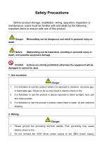
Safety Precautions Before product storage, installation, wiring, operation, inspection or maintenance, users must be familiar with and abide by the following important items to ensure safe use of this product. Mishandling can be dangerous and result in personal injury or Notice Mishandling can be hazardous, resulting in personal injury or death, and possible equipment damage. Prohibit Actions are strictly prohibited, otherwise the equipment will be damaged or cannot be used. 1. Use occasions Danger 1. It is forbidden to use the product where it is exposed to moisture, corrosive gas, or flammable...
Open the catalog to page 2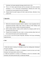
otherwise it will cause equipment damage, electric shock or fire. 3. The U, V, W motor output terminals must be connected to the motor connection terminals U, V, W in one-to-one correspondence, otherwise the motor may overspeed and cause equipment loss and casualties. 4. Please fasten the power supply and motor output terminals, otherwise it may cause a fire . Before the mechanical equipment starts to operate, it must cooperate with the appropriate parameter setting value. Failure to adjust to proper settings could result in loss of control or failure of mechanical equipment. Before starting...
Open the catalog to page 3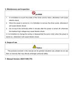
5. Maintenance and inspection prohibit 1. It is forbidden to touch the inside of the driver and its motor, otherwise it will cause electric shock. When the power is turned on, it is forbidden to remove the driver panel, otherwise it will cause electric shock. Do not touch the terminals within 5 minutes after the power is turned off, otherwise the residual high voltage may cause electric shock. 4. It is forbidden to change the wiring or disassemble the servo motor when the power is turned on, otherwise it will cause electric shock. 6. Scope of use Notice The products involved in this manual are...
Open the catalog to page 4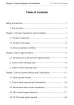
Chapter 1 Product Inspection and Installation FT2 Servo User Manual Safety precautions ································································································· - 1 1. Use occasion ·····························································································- 1 Chapter 1 Product Inspection and Installation ······································ - 1 1.1 Product inspection ·············································································· - 1 1.2 Product front panel ·············································································-...
Open the catalog to page 5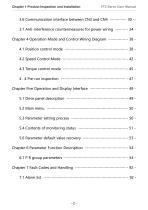
Chapter 1 Product Inspection and Installation FT2 Servo User Manual 3.6 Communication interface between CN3 and CN4 ··················- 30 -3.7 Anti-interference countermeasures for power wiring ············· - 34 Chapter 4 Operation Mode and Control Wiring Diagram ····················· - 38 4.1 Position control mode ········································································ - 38 4.2 Speed Control Mode ··········································································· - 42 4.3 Torque control mode ···········································································-...
Open the catalog to page 6All Guangdong Dingshen Electric Technology Co. LTD catalogs and technical brochures
 ST300 Inverter User Manual
51 Pages
 ST310 Inverter User Manual
104 Pages
 Servo Motor Selection Manual
10 Pages
 ST330 Inverter User Manual
106 Pages

- Servo-motor
- Servo-amplifier
- High-performance servo motor
- AC servo-motor
- Fieldbus servo-drive
- Controller servomotor
- AC servo-amplifier
- 220 V servo-motor
- Industrial servo motor
- Robotic servo-motor
- EtherCAT servo-amplifier
- CANopen servo-amplifier
- Machine tool servomotor
- Servomotor with built-in encoder
- Servo-motor with brake
- Servo motor servo-amplifier
- High-torque servomotor
- High-precision servomotor
- Asynchronous servo drive
- High-speed servomotor