- Catalogs
- Guangdong Bell Experiment Equipment Co., Ltd
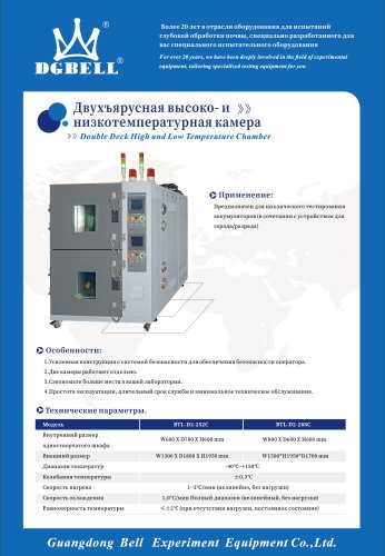
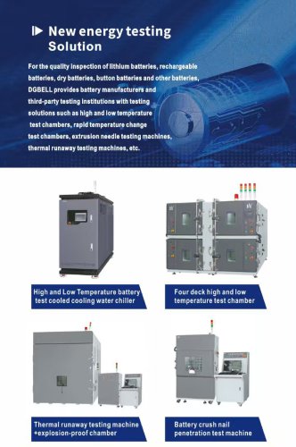
- thermal runaway test chamber BE-8401
- Company
- Products
- Catalogs
- News & Trends
- Exhibitions
thermal runaway test chamber BE-8401
1 /1Page

thermal runaway test chamber BE-8401
1 /1Page
Catalog excerpts

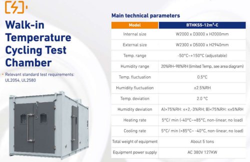
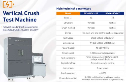
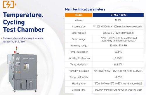
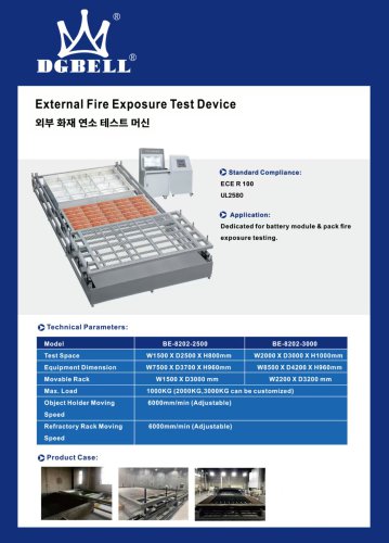
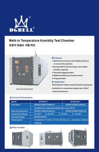
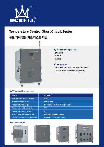
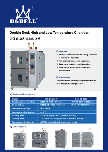
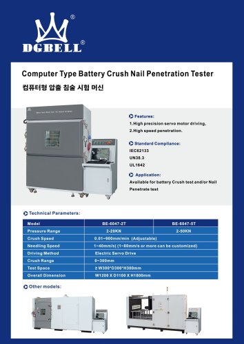
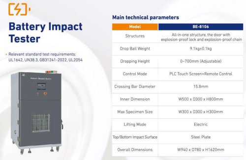
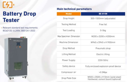
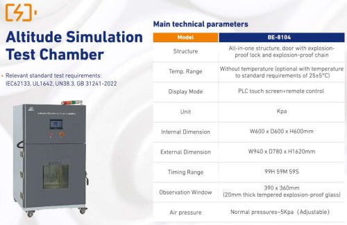
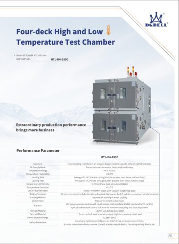
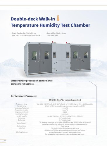
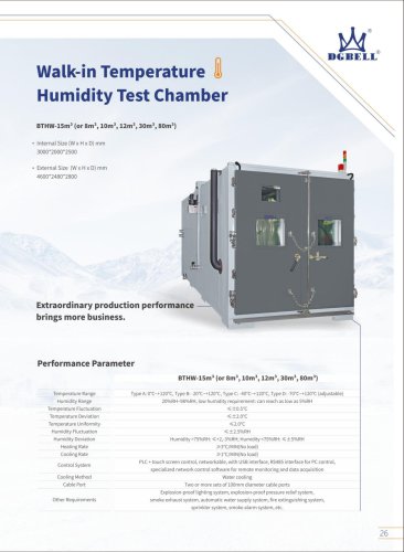
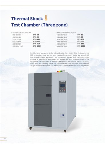
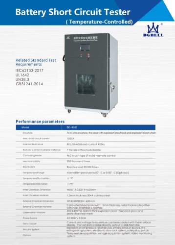
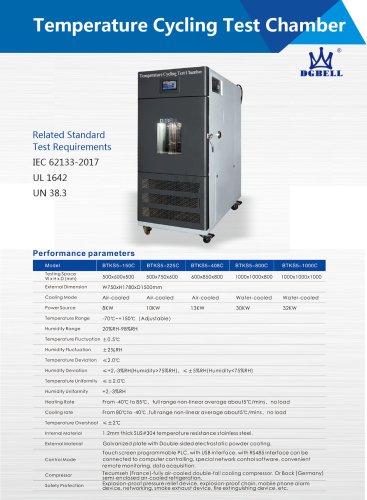
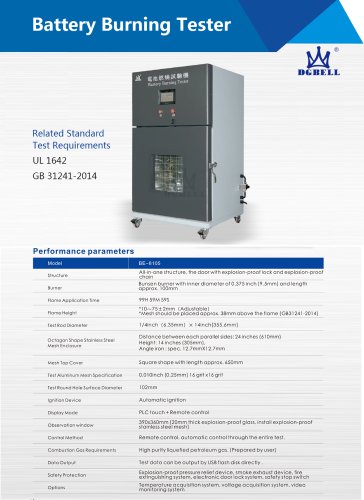
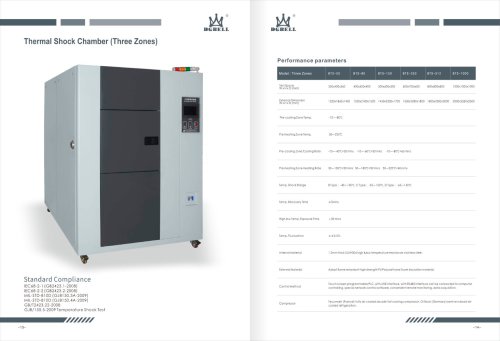
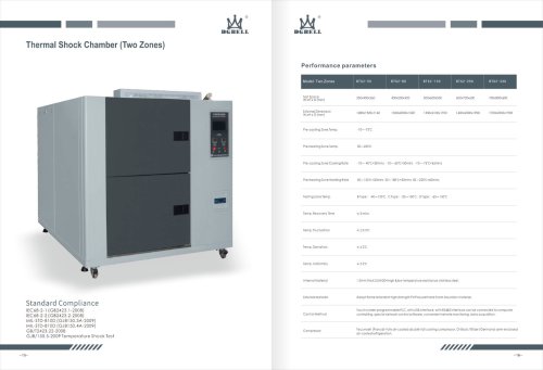
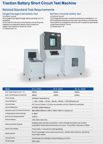
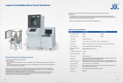
Thermal runaway testing machine Thermal runaway test chambers Thermal runaway tester Performance parameters Model BE-8401 Trigger Mode Overcharging and heating (Optional) Heating Mode Channel 2 channel(1 in common used, 1 for spare) Max. Heating Power 3KW, Single channel Power Adjust Mode Changed the heating tube with different capacity + Adjust the input current. Power Supply AC 220V 50Hz Max. Overcharging Voltage 10V and 100V Voltage Acquisition Channel 10 channel,20 channel, 40 channel (Optional) Temp. Acquisition Channel 10 channel, 20 channel, 40 channel (Optional) Control Mode PLC+PC control (PC and main chamber integrated) Control Host Overall Dimension W700 X D650 X H1 360mm Explosion-proof Chamber Dimension W2000xD3000xH2000mm (Optional) Total Weight Power Supply AC 220V, 7.0KW Related Standard Test Requirements Test objects The test object is the whole vehicle or the complete vehicle-borne Li-ion battery system or the subsystem of vehicle-borne lithium-ion battery system, including lithium-ion batteries and electrically connected lithium-ion batteries. Test conditions: The test shall be started under the following conditions. 1.Testing should be started at temperature higher than 0 °C, relative humidity 15%~90%, and the atmospheric pressure 86~106 kpa. 2.Before testing, The SOC of the test object should be adjusted to 90% or 25% of the normal SOC working range specified by the manufacturer. 3.Before testing, all the test device must be running normally. 4. The test objects should be modified as little as possible when testing, and the manufacturer should submit a list for all changes. 5. Testing should be at the room temperature or wind Speed is not more than 2.5 km/h. Thermal runaway trigger object Heating and needling are recommended as candidates for thermal runaway test of lithium ion battery systems. Manufacturers can choose one of them. Heating triggered thermal runaway Use planar or rod-shaped heating devices, and their surfaces should be covered with ceramic, metal or insulating layers. If the block heating devices has the same size as lithium-ion batteries, the heating device can be replaced one of the lithium-ion batteries to make direct contact with the surface of the trigger object; For thin film heating devices, they should always be attached to the surface of the trigger object. Wherever possible, the heating area of the heating device should not bigger than the surface area of the lithium ion battery; The heating surface of the heating device is directly contacted with the surface of the battery, the position of the heating device shall correspond to the position of the temperature sensor specified in 1.6; Start the heating device immediately after installation, the trigger object is heated by the maximum power of the heating device, the power of the heating device is shown in Table A1.1, but it can not be mandatory. Stop triggering when thermal runaway happened or the temperature of the 1.6-defined that the temperature of monitoring point reaches 300°C. Test Objects Energy E(Wh) Max. Power of Heating Device (W) E<100 30~300 100=E<400 300~1000 400= E<800 - 300~2000 E=800 >600 According to one or more of the following conditions,the manufacturer shall determine whether thermal runaway happened or not, and shall specify the conditions for determining thermal runaway in the technical documents. 1.Voltage drop occurred at test objects. 2.The temperature of the monitoring point reaches the maximum operating temperature specified by the manufacturer. 3.The temperature heating rate of the monitoring point. 4.Other parameters set by the manufacturer. Monitoring of voltage and temperature Monitoring the voltage and temperature of the trigger object to determine whether thermal runaway happens. When monitoring the voltage, the original circuit should not be changed. Monitoring temperature is defined as temperature A(the highest surface temperature of the trigger object in the testing).The sampling interval of temperature data should be less than 1s, the accuracy should be +2°C, and the diameter of temperature sensor cusp should be less than 1 mm. When the needle is triggered, the position of the temperature sensor should be as close as possible to the short circuit point. Trigger Object Temperature Sensor Needling Point Table A.1 Schematic of temperature sensor placement during needle triggering When heating is triggered, temperature sensors are arranged on the side far from heat conduction. Which means on the opposite side of the heating device (Table. A.2). If itis difficult to install temperature sensors directly, they can be arranged in a position where continuous temperature rise of the trigger object can be detected. Shell battery and pouch cell Cylindrical Cell Heating Device Heating Device (resistance wire) Temperature Monitoring Cylindrical Cell DGBELL
Open the catalog to page 1All Guangdong Bell Experiment Equipment Co., Ltd catalogs and technical brochures
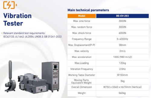 GDBELL Vibration Tester
1 Page
 Battery Safety Test Chamber C
28 Pages
 Environmental Test Chamber C
14 Pages
 climate test chambers
1 Page
 Leak testing machine
1 Page
 Drop tester BE-8206-1500
1 Page


Archived catalogs


- Kiln
- Chamber kiln
- Heat treatment kiln
- Electric furnace
- Chiller
- Temperature test chamber
- Material test machine
- Automated testing machine
- Climatic test cabinet
- Digital temperature control
- Quality control test cell
- Liquid recirculation chiller
- Computer-controlled test machine
- Humidity test cabinet
- Drying kiln
- Environmental test chamber
- Digital tester
- Laboratory kiln