- Catalogs
- GROENEVELD-BEKA
- Original operating and assembly manual
Original operating and assembly manual
1 /19Pages

Original operating and assembly manual
1 /19Pages
Catalog excerpts

LUBRICATION SYSTEMS BY TIMKEN N30201. diund uoneouqni eseejg jedns-d 6M21V9 © Baier + Koppel GmbH + Co. KG 2020
Open the catalog to page 1
© Baier + Köppel GmbH + Co. KG 2020
Open the catalog to page 2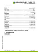
Technical data The grease lubrication pump is subsequently called a device. 2. Applicable documents Dimensional drawing AZ Connection diagram ES Declaration of incorporation © Baier + Köppel GmbH + Co. KG 2020
Open the catalog to page 3
General safety instructions Everybody who is in charge of the assembly, start-up, maintenance and operation of the device must read these instructions carefully prior to assembly and start-up of the device at the machine! Furthermore, this manual must always be available at the site of operation! Basic instructions for setup, operation and maintenance can be found below. 3.1 Safety instructions Observe the general safety instructions within this key chapter as well as the special safety instructions in other chapters of this operating and assembly manual. Warning of electrical voltage. Safety...
Open the catalog to page 4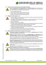
GROENEVELD-BEKA LUBRICATION SYSTEMS BY TIMKEN 3.3 Hazards in case of non-observance of the safety instructions a Results of non-observance of the safety instructions can be hazards to persons, for the environment and the /|\ device. Non-observance of the safety instructions may result in the loss of any liability claims. The non-observance / ; \ could more specifically result in the following hazards (for example): • Failure of important device functions. • Failure of prescribed methods regarding maintenance and repair. • Danger to persons by electrical, mechanical and chemical effects. • Danger...
Open the catalog to page 5
GROENEVELD-BEKA LUBRICATION SYSTEMS BY TIMKEN Operational safety of the device is only guaranteed when it is appropriately applied as indicated in the operating and assembly manual. Never exceed or fall below the limit values, as stated in the technical data. Avoid electrostatic discharge! There are electronic components integrated into the devices which might be destroyed by electrostatic discharge. Observe the safety precautions against electrostatic discharge according to DIN EN 613405-1/-3. Ensure that the environment (persons, workplace and packing) is well grounded when handling these devices....
Open the catalog to page 6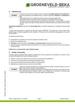
N30201. diund uoneouqni 9SB9J0 jgdns-d 6M21V9 GROENEVELD-BEKA LUBRICATION SYSTEMS BY TIMKEN The device is part of a central lubrication system. It serves for conveying lubricant for the lubrication of machines as described in this operating manual. The device is approved for industrial and commercial use only. Only operate the device if it is installed in/at another machine and operated together with it. Only lubricants which comply with the machine manufacturer's specifications may be conveyed. The device must only be used according to the technical data (see chapter 1 ..Technical data”). The...
Open the catalog to page 7
Use suitable lifting devices for transport. Do not throw the device or expose it to shocks. Secure the device against toppling down or slipping during transport. The device may only be transported completely empty. Observe all valid safety and accident prevention regulations for the transport. Wear suitable protective equipment if necessary. Keep adequate distance to suspended loads. The transport help or the elevating device must have the adequate carrying capacity. When storing the device pay attention that the storage area is cool and dry in order to avoid corrosion of the individual parts...
Open the catalog to page 8
GROENEVELD-BEKA LUBRICATION SYSTEMS BY TIMKEN /•\ Comply with the following conditions when assembling a complete machine from this device and other components. / ; \ Mind a proper and eco-friendly assembly without impairment of persons’ health and safety: Assemble the device in balance on the installation location in order to ensure safe operation. Observe the information on the fastening holes given in the dimensional drawing. When selecting the set-up location, please mind that the device should be protected against ambient and mechanic influences. Ensure full access, e.g. for filling with...
Open the catalog to page 9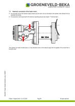
Hydraulic connection of the hydro motor The connection line for the hydraulic supply pressure and the return can be connected to the hydraulic motor (thread G1/2) as requested (red arrows). All components must be approved for the maximum operating pressure (see chapter 1 “Technical data“). The customer can install a throttle piece or a 2-way directional valve on the hydraulic supply line for regulation of the volume flow to the hydro motor. © Baier + Köppel GmbH + Co. KG 2020
Open the catalog to page 10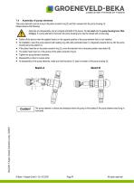
LUBRICATION SYSTEMS BY TIMKEN The pump elements must be hung in the piston eccentric ring (2) and then screwed into the pump housing (3). Please observe the following: Assembly and disassembly only at complete standstill of the device. Do not reach into the pump housing bore. Risk / f \ of injury. If a pump element is removed, the pump housing bore must be closed with a screw plug. • Switch off the device when the agitator blade is in the opposite position of the pump element that is to be installed. • At installation, insert the pump element with sealing ring with partly extracted piston (1)...
Open the catalog to page 11
GROENEVELD-BEKA LUBRICATION SYSTEMS BY TIMKEN • The device is designed for standard multi-purpose greases up to NLGI cl. 2. • Use lubricants with high-pressure additives. • Only use lubricants of the same soaping criteria. • Do not use any lubricants with solids content (lubricants with solids content on request). 8.2 Filling with lubricant • Observe the machine manufacturer's lubricant details! Only use lubricants according to machine manufacturer's specifications! • Collect leaking lubricant in a suitable reservoir and dispose it professionally! • Observe the safety data sheet of the lubricant...
Open the catalog to page 12
N3020L diund uoneouqni 9SB9J0 jgdns-d 6M21V9 GROENEVELD-BEKA LUBRICATION SYSTEMS BY TIMKEN • Remove the screw plug and replace it by a coupling plug with reducer (article no. 10101421 and 10149043). • Remove the optional protective cap (article no. 10101446) of coupling plug. • Press out about 10mm of lubricant from the suitable filling gun (manually operated or pneumatic). • Connect the filling pump to the filling connection or the coupling plug and fill the device up to the maximum level. • Put the protective cap back on the coupling plug. The speed of the hydraulically driven hydro motor is...
Open the catalog to page 13All GROENEVELD-BEKA catalogs and technical brochures


Archived catalogs
 BreakAlube
4 Pages
 autobus
2 Pages
 Speciale actie
1 Page
 Speed Limiter
4 Pages

