


Centrifugal Fan Performance Supplement - Single Width

Centrifugal Fan Performance Supplement - Single Width
- Motor Selection: Greenheck centrifugal fans can be equipped with any suitable motor for the fan size and performance. Tables are provided for motor frame sizes and maximum motor frame sizes for different fan arrangements.
- Maximum Motor Frame Sizes: Specific motor size limitations are outlined for arrangements 9 and 10 based on enclosure type and voltage.
- Motor Starting Torque: The motor must drive the fan at operating speed and accelerate the fan wheel, shaft, and drive. A formula is provided for calculating the required motor starting torque.
- V-Belt Drives: Discusses advantages of constant and variable speed drives, with recommendations for motors of 15 HP and larger.
- High Temperature Operating Limits: Provides correction factors for maximum RPM at high temperatures and outlines material and arrangement options for different temperature ranges.
- Wheel Moments of Inertia: Lists moments of inertia for steel and aluminum wheels, with aluminum being one-third of the value shown for steel.
- Fan RPM Limitations: Maximum allowable wheel RPMs are provided for fans operating at 70°F, with derating factors for higher temperatures.
- Effects of Air Density: Discusses the impact of air density on fan performance, particularly at high suction pressures at the fan inlet.
- Effect of Installation on Performance: Installation factors that can affect fan performance are discussed.
- Sound Performance Testing: Details procedures for testing sound performance, including the use of AMCA standards.
- Tabulated Air Performance: Provides extensive tables of air performance data for various fan sizes.
- Fan Curves and Sound Power Ratings: Includes fan curves and sound power ratings for different fan configurations.
- Fan Sizes: Dimensional data is provided for fan sizes ranging from 7 to 73, with different arrangements.
- Computer Aided Product Selection Program (CAPS): Greenheck offers a CAPS program for product selection, along with online resources for product literature and installation manuals.
- To-Scale Drawings and Specifications: CAD drawings and detailed specifications are available online or through the CAPS program.
The document provides a detailed example of selecting a fan for specific conditions, such as an elevation of 2000 feet and an air temperature of 150°F. Key steps include determining the correction factor from a chart, adjusting the static pressure, and calculating the required fan RPM and brake horsepower (BHP). For high-temperature operations, the motor must handle increased loads at lower temperatures, requiring a correction factor for air density.
System effect factors impact fan performance, particularly when duct turns are near the fan discharge. To maintain optimal performance, at least three duct diameters of straight ductwork should be between the fan discharge and any turns. The document includes curves showing system effect factors for various duct configurations.
Fan performance can be reduced by improper inlet and discharge configurations. Recommendations include maintaining a clearance of one fan wheel diameter between the fan inlet and walls, and ensuring proper duct design to avoid inlet spin and free discharge issues.
Sound tests are conducted according to AMCA Standard 300, using a reverberant room and a Reference Sound Source (RSS) for accurate sound power level determination. The document explains the test setup and provides sound power data for various fan speeds and configurations, including duct end corrections.
- Model: BISW
- Wheel Diameter: 18 1/4 in. and 20 in.
- Outlet Area: 1.92 ft2 and 2.30 ft2
- Tip Speed: 4.78 x RPM and 5.24 x RPM
- Maximum RPM Classes: I (2099), II (2738), III (3450), IV (3800)
- Maximum BHP: Calculated as (RPM/1206)3 and (RPM/1035)3
- Minimum Starting HP: 1/3 and 1/2
- Static Pressure and RPM/BHP data are provided for various CFM (Cubic Feet per Minute) values.
- Sound Power Levels are given in decibels, calculated per AMCA Standard 301, for both inlet and outlet conditions.
- Inlet and outlet sound power levels are provided for different RPM and %WOV (Width of Opening Variation) conditions.
- Sound levels are expressed in decibels, with A-weighted sound ratings calculated per AMCA International Standard 301.
- Performance ratings do not account for accessories.
- Power ratings exclude transmission losses.
- Sound power levels include duct end correction effects.
- Ensure installation follows the specified arrangement and type for optimal performance.
- Consider sound power levels in design to meet noise requirements.
- Model: AFSW Arrangement 1, Installation Type B (free inlet, ducted outlet).
- Wheel Diameter: 22 1/4 in. and 24 1/2 in.
- Outlet Area: 2.85 ft2 and 3.45 ft2.
- Tip Speed: 5.83 x RPM and 6.41 x RPM.
- Maximum RPM: Class I - 1885, Class II - 2459, Class III - 3098.
- Maximum BHP: Calculated as (RPM/969)3 and (RPM/824)3.
- Performance ratings do not include the effects of accessories.
- Power rating (Bhp) excludes transmission losses.
- Static pressure and RPM data are provided for various CFM (Cubic Feet per Minute) values.
- Sound power levels are given in decibels, referenced to 10-12 watts, calculated per AMCA Standard 301.
- Inlet and outlet sound power levels are provided for different RPM and %WOV (Width of Opening Variation).
- A-weighted sound ratings are calculated per AMCA International Standard 301.
- Maximum Open Motor Frame Size varies by arrangement and class.
- Minimum Starting HP is 1/2.
- Density considerations: 0.075 lb/ft3 and 1.2 kg/m3.
- Ensure performance ratings are considered without accessories.
- Adhere to maximum RPM limits for each class to avoid operational issues.
The document provides detailed specifications for two models of fans, the 54 AFSW and 60 AFSW. Key parameters include wheel diameter, outlet area, tip speed, maximum brake horsepower (BHP), minimum starting horsepower, and maximum revolutions per minute (RPM) for different classes. For the 54 AFSW, the wheel diameter is 54 1/4 inches, and the outlet area is 16.92 ft². The maximum RPM varies by class: Class I is 731, Class II is 952, and Class III is 1200. For the 60 AFSW, the wheel diameter is 60 inches, and the outlet area is 20.7 ft², with maximum RPMs of 661, 861, and 1085 for Classes I, II, and III, respectively.
The document includes extensive tables showing RPM, BHP, and static pressure for various cubic feet per minute (CFM) values. These tables are crucial for understanding the performance characteristics of the fans under different operating conditions. The tables are divided into sections based on static pressure increments, providing RPM and BHP values for each CFM level.
Sound power levels are provided in decibels, calculated per AMCA Standard 301. The document lists inlet and outlet sound power levels for different RPM and percentage of wide open volume (WOV). The sound power levels are categorized by installation type B, which includes a free inlet and ducted outlet. The A-weighted sound ratings are also provided.
Graphs in the document illustrate the relationship between static pressure and volume, as well as RPM and BHP. These graphs help visualize the performance curves and are essential for selecting the appropriate fan model based on specific application requirements.
The document advises not to select to the left of the system curve, indicating the importance of operating within the specified performance range to ensure efficiency and avoid damage. It also notes that performance ratings do not include the effects of accessories, and power ratings do not account for transmission losses.
- Model 66 AFSW: Wheel Diameter = 66 in., Outlet Area = 25.05 ft², Tip Speed = 17.28 x RPM, Maximum RPM Class I = 601, Class II = 783, Class III = 987.
- Model 73 AFSW: Wheel Diameter = 73 in., Outlet Area = 30.64 ft², Tip Speed = 19.11 x RPM, Maximum RPM Class I = 543, Class II = 708, Class III = 892.
- Performance is certified for free inlet and ducted outlet configurations.
- Power ratings (Bhp) do not include transmission losses.
- Sound power levels are provided in decibels, calculated per AMCA Standard 301.
- Values are given for both inlet (Lwi, LwiA) and outlet (Lwo, LwoA) sound power levels.
- Tables provide RPM, BHP, and static pressure data for various CFM (Cubic Feet per Minute) values.
- Data is segmented by static pressure ranges from 0.25 to 14.00 inches wg (water gauge).
- Maximum BHP is calculated as (RPM/154)³ for Model 66 and (RPM/130)³ for Model 73.
- Minimum Starting HP is 25 for Model 66 and 40 for Model 73.
- Do not select to the left of the system curve as indicated in the performance charts.
Catalog excerpts

Single-Width Centrifugal Fan Performance Supplement • Engineering Information • Air Performance • Sound Performance • Dimensional Data
Open the catalog to page 1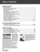
Table of Contents Engineering Data Air and Sound Performance Data Dimensional Data Sizes Sizes Sizes Sizes All Greenheck products are supported by the industry’s best product literature, electronic media, and Computer Aided Product Selection program, CAPS. Online, you can also find electronic copies of our product literature as well as storage, installation and maintenance information in our Installation and Operation Manuals. And, of course, you can always count on the personal service and expertise of our national and international representative organization. To locate your nearest Greenheck...
Open the catalog to page 2
Engineering Data Motor Selection Greenheck centrifugal fans can be supplied with any motor that is commercially available, and appropriate for the fan size and performance required. The tables show motor frame sizes corresponding to those motors readily available. See the maximum motor frame size charts below if motor is for arrangement 9 or 10 fans. Notes: 1. Fractional horsepower motor frame sizes shown may change due to variations in voltage, special features and manufacturer. 2. Motors shown are ball bearing, continuous duty. Two speed motors are two winding, 1/3 reduction in RPM. 3. Single-phase...
Open the catalog to page 3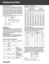
Engineering Data Motor Starting Torque When selecting a motor for a centrifugal fan, the motor must be capable of driving the fan at operating speed and also capable of accelerating the fan wheel, shaft and drive to the operating speed. Moments of inertia are shown for steel wheels. Aluminum wheels are one-third of the value shown. The fan performance tables and curves in this catalog show the brake horsepower required to operate the fan once it is brought to operating speed. For applications requiring a large air volume at a low static pressure, the BHP required at the fan’s operating RPM may...
Open the catalog to page 4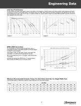
Engineering Data Inlet Vane Performance As inlet vanes are closed, they impart a spin to the airflow in the direction of wheel rotation and reduce airflow, static pressure and brake horsepower as shown in the graphs below. The graphs show how CFM, static pressure and brake horsepower are affected as inlet vanes are modulated from 100% open to 0% open in a typical variable air volume system. Graph 3 provides RPM and BHP correction factors for fans equipped with inlet vanes. 100 80 % Peak Brake Horsepower % Peak Static Pressure % Wide Open Volume % Wide Open Volume RPM & BHP Corrections To compensate...
Open the catalog to page 5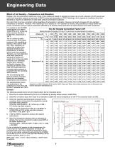
Engineering Data Effect of Air Density – Temperature and Elevation Ratings in the fan performance tables and curves of this catalog are based on standard air (clean, dry air with a density of 0.075 pounds per cubic foot, barometric pressure at sea level of 406.75 inches wg, temperature of 70°F). Selecting a fan to operate at conditions other than standard air requires an adjustment to both static pressure and brake horsepower. One cubic foot of air has a constant volume regardless of temperature or elevation. However, air density changes with non-standard temperature or elevation. Therefore,...
Open the catalog to page 6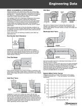
GOOD GOOD GOOD Inlet spin is a frequent cause of reduced fan performance. The change in fan performance is a function of the intensity of spin GOOD POOR and not easily defined. The best solution is proper duct GOOD design and POOR n tio airflow patterns. a Ro t Length of effect factors. The static pressure be expressed in terms of systemStraight Duct for selection oftion fans equals the system static pressure plus the the GOOD a system teffect factor. GOOD ion Turning Turning Vanes Vanes POOR POOR POOR Length POOR of Straight Duct Static pressure losses due to inlet and discharge conditions can...
Open the catalog to page 7
Sound Performance Testing AMCA Licensed Ratings Sound tests of Model BISW and AFSW were conducted in Greenheck Fan Corporation’s AMCA Accredited sound laboratory in accordance with AMCA Standard 300. Inlet and outlet sound ratings comply with AMCA Publication 311, qualifying these models to bear the AMCA Seal for Sound and Air Performance. The sound power levels published here can be compared directly with those of other similarly rated fans, or used as a baseline to determine sound levels in occupied spaces. The sound data in this brochure is the result of extensive testing, which included both...
Open the catalog to page 8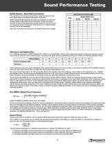
Sound Performance Testing Outlet Sound – Duct End Corrections This correction accounts for sound that is reflected back into the duct where there is an abrupt termination of the duct. AMCA Standard 300 requires that outlet sound power for fans with ducted outlets include Duct End Corrections. These corrections account for any sound power that may be present in the duct but is not measured in the reverberant room, because it is reflected back into the duct at the discharge. Duct end corrections are included in all outlet sound power ratings. Tolerance and Application The certification process...
Open the catalog to page 9
Sample Fan Selection Sound and Air performance are identical for Greenheck Series 21 and 41 centrifugal fans. The following example explains the model number code for both series of centrifugal fans. The purpose of these two pages is to demonstrate the manual centrifugal fan selection process. These pages also contain helpful tips to check your fan selection, as well as a step-by-step set of instructions on how to use this manual to properly select a centrifugal fan. An important point to remember when manually selecting a centrifugal fan is that more than one fan is available to meet the desired...
Open the catalog to page 10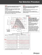
Fan Selection Procedure STEP 1 Enter the performance table with the desired CFM and Ps. Obtain the fan RPM, BHP and Class. STEP 2 Enter the Fan Curve with the desired CFM and Ps. Obtain the fan operating point, % WOV, Motor HP and verify fan class by curve shading. EXAMPLE For this example, we will use 19,100 CFM at 4.0 Ps. This gives us a fan RPM of 995, requiring 17.2 BHP, with Class I construction. EXAMPLE For this example, the fan operating point is at 60% WOV using a 20 HP motor. NOTE: If your specific fan selection requires inlet vanes or if the fan operating point is not at standard air...
Open the catalog to page 11All Greenheck catalogs and technical brochures
 building value in air WORLDWIDE
56 Pages
 Model TAUD TAUB-CA
24 Pages
 Model TAUB-L/H
16 Pages
 Model AX
8 Pages
 Models QEI QEID
52 Pages
 Models TCB TCBRU TCBRS
32 Pages
 Inline Fans (Models SQ and BSQ)
48 Pages
 Greenheck Coils Brochure
8 Pages
 Bypass Air Plenum
2 Pages
 Belt Drive Duct Fans (Model BDF)
12 Pages
 Models IDHC and IDHB
8 Pages
 Centrifugal Roof Exhaust Fans
52 Pages
 Industrial Process Fans
12 Pages
 AMCA & Greenheck
2 Pages
 Air Measuring Products
8 Pages


