 Website:
Graphtec
Catalog excerpts

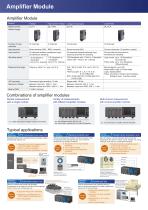
Embedded in the device to create the system Connected to the PC for measuring with the GL7000 (no display module) Suitable for a variety of measurements due to flexible module combinations Voltage Module • The output of various sensors such as displacement, pressure, wind speed, etc Cell voltage of the battery. Voltage/Temperature Module • Measuring temperature and voltage High Speed Voltage Module inverter system, vibration test, drop test Logic/Pulse Module • Timing of system control signal, encoder output, rotational speed, flow rate, etc released sequentially High Voltage Module • Measurement of the high voltage in the power line of equipment, Electric or Hybrid Vehicle testing, etc. Voltage Output Module • An analog voltage corresponding to the captured data is output. Simulation testing by the actual measured data, the vibration test, etc. • Measuring the output of sensor using the strain gauge. Measurement of the load, displacement, vibration, acceleration, torque, pressure, etc. Charge Module • Measuring the output of sensor using the Piezoelectric device. Measurement of the vibration, acceleration, Power Measurement Module • Measuring the voltage, current and power. Measurement of the power line of the device, etc. Excluding the function module as the Display module or SSD module. The Input/Output cable (B-513) is required for connecting the signal. The Autobalance signal input and the Busy signal output are used in the DC Strain Module. The alarm signals are output on the terminal block attached to the main module as standard accessory. It is available on the Logic/Pulse module. Volt/Temp, module: The alarm is detected in the sampling interval when the sampling interval is shorter than 5 seconds. The alarm is detected every 5 seconds when the sampling interval is longer than 5 seconds. Other modules: The alarm is detected every 1ms when the sampling interval is shorter than 1ms. The alarm is detected in the sampling interval when the sampling interval is set between 2ms to 5 seconds. The alarm is detected every 5 seconds when the sampling interval is longer than 5 seconds. It is available when the captured data is saved to the built-in RAM. The pre-trigger function may not work in combination with the trigger settings. The result of real time calculation is displayed in the digital display mode. When the captured data destination is set to the built-in-RAM, the captured data is not maintained after a power failure. The built-in Flash or the SD memory card may be damaged by a power failure if it is being accessed to write data. If the memory device is not damaged, the closed data file is maintained. The file is closed every one minute while data is being captured. The USB drive mode is started by setting of the switch on the main module. It can be also started when the power is turned on while pressing the key on the display module. *10. The SD memory card is not included as a standard accessory. The SSD module is an option. *11. The capacity for saving the data is set to one third of available memory when the captured data destination is set to a device other than the built-in-RAM. The sampling speed is limited up to *12. The Sync cable (B559) is required when this function is used. The GL-Connection software is required when the synchronizing function is used. *13. The SP2 or higher service pack need to be installed. *14. The captured data that is saved to the built-in-RAM or SSD cannot be saved to the PC in real time. The data in the built-in-RAM or SSD needs to be transferred to the PC after data capture is complete. *15. Most operations can be selected by both the touch panel and keys. *16. When the display module is mounted at an angle using the bracket, the display module is connected to the main module by a LAN cable that is attached to the display module as a standard accessory. *17. The sampling speed in the GL7000 is limited to the fastest sampling speed of attached signal conditioning module. When the specified sampling speed is faster than the module, the sampling is done in fastest sampling on the module. The same value is stored to the memory device in the specified sampling speed until data is renewed by the next sampling. Brand names and product names listed in this brochure are the trademarks or registered trademarks of their respective owners. Specifications are subject to change without notice. \ RoHS Compliant model Graphtec Corporation 503-10 Shinano-cho, Totsuka-ku, Yokohama 244-8503, Japan Email : webinfo@graphtec.co.jp ^^^^ http://www.graphteccorp
Open the catalog to page 1
The new generation data acquisition unit It can measure the desired signal according to the needs and can expand into other applications adding different amplifier modules. It can be attached to a display module having a touch panel, used as a stand-alone unit or embedding into a system. The number of channels and measurement types can be added to the amplifier module Alarm output terminal (included in the main module) Main module Display module (option) Module is fixed by a screw The amplifier module can be expanded to accommodate a wide variety of measurements A wide variety of...
Open the catalog to page 2
Amplifier Module Amplifier Module Module High Speed Voltage Model number Number of input channels Input terminal Circular connector (10 position, socket) Input method All channels isolated unbalanced input, simultaneous sampling All channels isolated balanced input, scanning channels for sampling All channels common ground, simultaneous sampling Sampling speed 1 M Samples/s to 1 k Samples/s to 1 Sample/h 1 Sample/h (1ms to 1hr. interval) (1μs to 1hr. interval) 100 Samples/s with 1-10ch to 1 Sample/h (10ms with 1-10ch to 1hr. interval) Logic mode: up to 1 M Samples/s (1μs interval) Pulse...
Open the catalog to page 3
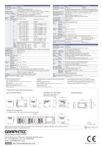
Voltage/Temperature Module Specifications Model number GL7-M 10 channels Number of input channels All channels isolated balanced input, Input method Scans channels for sampling, Screw terminal (M3 screw) Sampling speed 100 Samples/s with 1-10ch to 1 Sample/h (10 ms at 1-10ch to 1 hr. interval) MeasureVoltage 20, 50, 100, 200, 500 mV, 1, 2, 5, 10, 20, 50 V, and 1-5 V/F.S. ment range Temperature Thermocouple: K, J, E, T, R, S, B, N, and W (WRe5-26), RTD: Pt100, JPt100(JIS), Pt1000(IEC751) Humidity *1 0 to 100 % (using scanning function in 5V range, humidity sensor B-530) Measure- Voltage ±...
Open the catalog to page 4All Graphtec catalogs and technical brochures
-
G Metal Shield
2 Pages
-
FC9000
4 Pages
-
DLC1000
2 Pages
-
F-MARK2
2 Pages
-
GLT400
4 Pages
-
Petit LOGGERGL100
4 Pages
-
LCX603
2 Pages
-
CSX500 series
2 Pages
-
FC8600 series
2 Pages


