
- Catalogs
- Grand Growth
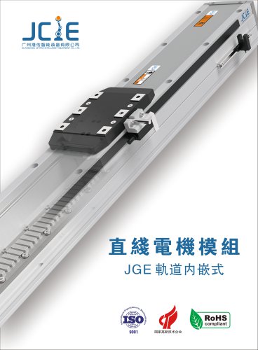
- JTY - Electric Cylinder Linear Module Catalogue


- Company
- Products
- Catalogs
- News & Trends
- Exhibitions
JTY - Electric Cylinder Linear Module Catalogue
JTY - Electric Cylinder Linear Module Catalogue
Embedded Electric Cylinder Series Overview
This document details specifications and ordering information for the JTY series embedded electric cylinders, specifically models JTY5 and JTY8, designed for single-axis linear motion applications.
1. Product Models and Specifications
- JTY5 Model: Maximum stroke of 600mm, maximum speed of 1000mm/s, motor capacity of 100W, ball screw diameter Ø12mm.
- JTY8 Model: Maximum stroke of 800mm, maximum speed of 1000mm/s, motor capacity of 200W, ball screw diameter Ø16mm.
2. Ordering Method and Model Coding
The model number is structured to include the following parameters:
- Base model (JTY5 or JTY8)
- Ball screw diameter (e.g., L12 for 12mm, L16 for 16mm)
- Ball screw lead (options: 2mm, 5mm, 10mm, 20mm for JTY5; 5mm, 10mm, 20mm for JTY8)
- Stroke length (50-600mm for JTY5, 50-800mm for JTY8, in 50mm increments)
- Motor position (BC: motor exposed, BM: motor bottom fold, BL: motor left fold, BR: motor right fold)
- Home sensor options (outside, motor side, opposite motor side, or none)
- Limit sensor options (outside, 1 or 2 pcs, or none)
- Motor brand (M: Mitsubishi, P: Panasonic, Y: Yaskawa, T: Delta, HU, HE: Huichuan, etc.)
- Motor capacity (100W or 200W depending on model)
3. Mechanical and Performance Parameters
- Ball Screw Drive: Utilizes precision ball screws with embedded guide rails for smooth linear motion.
- Repeatability: ±0.01mm for JTY5 and ±0.01mm for JTY8, ensuring high positioning accuracy.
- Anti-Rotating Accuracy: ±0°, designed to prevent piston rod rotation and maintain stability.
- Maximum Payload: Varies by model and stroke; for example, JTY5 supports up to approximately 100kg horizontally and less vertically, while JTY8 supports higher loads.
- Maximum Speed: Up to 1000mm/s for both models.
- Acceleration/Deceleration: Typically set at 0.2 seconds for smooth operation.
- Load Considerations: For strokes over 300mm, external auxiliary guide rails are recommended to support radial loads and prevent ball screw run-out. For JTY8, speeds should be reduced when stroke exceeds 750mm to avoid vibration.
4. Motor and Drive Compatibility
- Compatible servo motor brands include Mitsubishi, Panasonic, Yaskawa, Delta, and Huichuan.
- Motor shaft diameters differ by brand and power rating (e.g., Panasonic 200W motors have Ø11mm shafts, others Ø14mm).
- Brake options are available depending on horizontal (no brake) or vertical (with brake) installation requirements.
- Recommended servo motor and driver models are listed for each brand and power rating.
5. Sensor and Wiring Information
- Home and limit sensors are available in multiple mounting positions (outside, motor side, opposite motor side) or can be omitted.
- Wiring diagrams for general resistive loads and programmable controller connections are provided.
6. Installation and Usage Recommendations
- Avoid applying rotational torque to the piston rod to prevent deformation of the anti-rotating guide and internal components, which can cause increased resistance and sensor malfunction.
- Load extension distance should be zero without external auxiliary mechanisms.
- Vertical installation load capacities are lower than horizontal; auxiliary support is recommended for heavy or long-stroke applications.
7. Dimensional Data
Detailed dimensional tables provide lengths (L, L1), motor positions, and stroke increments for each model and motor configuration (motor exposed, bottom fold, left fold, right fold). Stroke increments are in 50mm steps from 50mm up to the maximum stroke (600mm for JTY5, 800mm for JTY8).
8. Product Variants and Samples
- Variants include general screw, clean screw, general belt, clean belt, steel mold screw, linear motor screw, embedded guide rail screw, and embedded belt guide rail samples.
- These variants cater to different application environments such as clean rooms or heavy-duty industrial use.
Critical Notes
- When stroke exceeds 300mm, auxiliary guide rails are necessary to prevent ball screw run-out and maintain precision.
- For JTY8, reduce speed when stroke exceeds 750mm to avoid vibration issues.
- Acceleration and deceleration settings are critical for smooth operation and are typically set at 0.2 seconds.
- Proper motor selection and brake configuration depend on installation orientation and load requirements.
This summary captures the essential technical specifications, ordering methods, mechanical parameters, motor compatibility, sensor options, and installation guidelines for the JTY embedded electric cylinder series.
Catalog excerpts
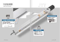
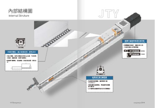
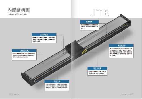
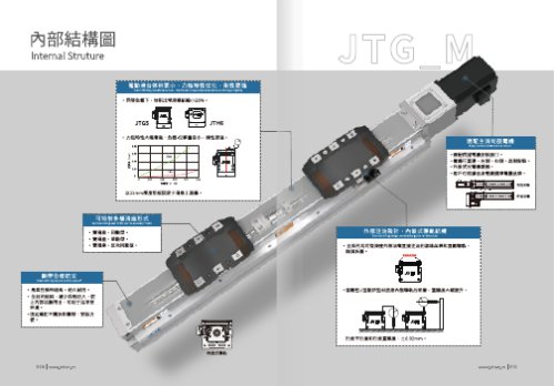
Internal Struture fifue' usm' nmnwmi ° c=o° High precision and zero rotation clearance
Open the catalog to page 1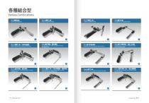
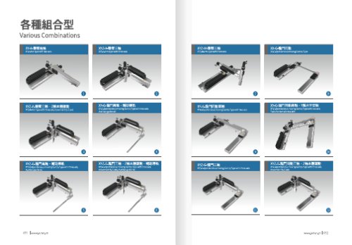
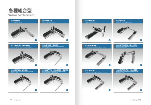
XY-A-Arm type with two axis XYZ-A-UffH^ XYZ-A-Arm type with three axis XYZ-M-HffH$i XYZ-M-Arm type with three axis XX-G-Spontaneous moving Gantry Type MZ-k-mEM ■ ZM*fl£BHi XYZ-A-Arm type with three axis,movement by Z axis xY-G-iip^$4 > XY-G-Spontaneous moving Gantry Type with two axis. Auxiliary guide rail XY-G-liP1Pi]®$4 > XY-G-Spontaneous moving Gantry Type with two axis. Y axis horizontal installatin xYz-G-mp^tt > XYZ-G-Spontaneous moving Gantry Type with three axis. Auxiliary guide rail XYZ-G-IIF1Z& . ZM*HSHl > MBmi XYZ-G-Spontaneous moving Gantry Type with three axis, movement by Z axis,...
Open the catalog to page 2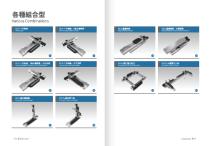
Various CombinationsXZ-F-+?M$A Cross two axis xz-f-+?®!4 > Cross two axis,Movement by Z axis xz-f-+?m$a > > 7Kw-^ ■ xz-f-+^®$4 > Cross two axis,Movement by zaixs,Horizontal installation Cross two axis,Horizontal installation XYY-G-IIP^^I^ XVY-G-Gantry combinatorial association XYYZZ-A-HimA$A XYYZZ-A-Arm type with six axis MovingArm Type with two axis MovingArmTypewiththreeaxis
Open the catalog to page 3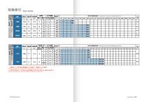
The highest speed is based on the maximum servo motor's rpm(3000),stepper motor is based on 500RPM. Written here is thestandard storke's maximum safe speed.if over this speed,it may casue serious virbration.
Open the catalog to page 4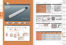
Ball screw drive Built-in guideway > ihtlto&f&m Shaft output deformation value Ll Ball screw lead mm Stroke pitch AC servo motor output Home sensor Acceleration and deacceleration \alue is set 0.4 second. General load: Such as relay or other resistive load When the stroke is over 300mm,the run-outofthe ballscrewwill occur. No externa I auxiliary mechanism, extension distance of load =0 Allowable installation load Programmable controller connection diagram No external auxiliary mechanism, extension distance of loaded. > ft*# ftRSitESfat Anti-rotating accuracy of rod Load in vertical installation...
Open the catalog to page 5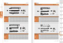
Motor expi Motor left BL/Motor right side BR axis
Open the catalog to page 6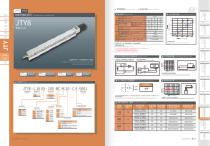
Ball screw drive Built-in guideway >1 When thestroke is over 750mm, the run-out of the ballscrew will occur. We recommend to low down the workingspeed under this circumstances. Acceleration and deacceleration value is set 0.4 second. When thestroke is over 300mm,the run-outofthe ballscrew will occur. fnl) Sensor layout General load: Such as relay or other resistive load Programmable controller connection diagram jc2e > ft*$Si»S Shaft output deformation value Allowable installation load ftm 800mm lOOOmm/s 200W Hm 016MM ^ Ordering method_ JTY8 - L 16 05 -100 -BC-M 20 - C 4 -0001 c ,®»fi Motor side...
Open the catalog to page 7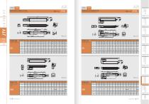
Motor exposed BC/Motor bottom side BM Motor left BL/Motor right side BR Motor exposed
Open the catalog to page 8
ffigmis&Kn Warranty JCIE robots are designed and manufactured to be free from defects in materials and workmanship. However,should any failure occur in the robot you purchaesd, the JCIE warranty coverage is as follows. This warranty will not apply in the following cases : Warranty Period This warranty is effective for a period of: % 12 months (one and a half years) after shipment from Taiwan factory,or % 2,500 hours of actual operation whichever comes first. % Fatigue arising due to the passage of time, natural wear and tear occurring during operation (natural fading of panited or plated surfaces,...
Open the catalog to page 9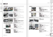
Measring Tools i. tH8?fTis/«ns Parallelism Testing / Height Testing. Measuring Tools: Dial Gauge N Dial Indicator Measuring Methods: 1. IMaB£ft£N£± Fix the actuator on granite. 2. KBJIHSftUUlM Fix the measuring tools on the actuator's slider. 2. Absolute Straightness Accuracy Testing Measuring Tools: Laser Interferometer Detection Measuring Methods: 1. l«ABCft«N:B± Fix the actuator on granite. 2. il«9B£K9ia99 Fix the measuring tools on the actuator's slider. 3. SnflSJn 77 3Ml!l is photo display. 4. ae5ijEniiju®£ Print the test report as a recoder. Belt Tension Testing Measuring Tools: fiffOMBMI...
Open the catalog to page 10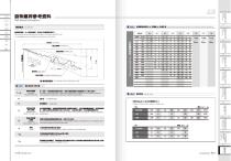
Actual value. mmmmsm • mdmmmmmmmm' ppisshshs ffijtgum m ■ - juumpii ■ • Specified Travel Specified travel. This value is determined by customer and maker as it depends on different application Specify The Target Value requirements. JMftSVS Cumulative Representative Lead Error Accumulated reference lead deviation. This is allowable deviation of specified travel. It is decided by both of the accuracy grade and effective thread length. Change Total relative lead variation Maximum width of variation over the travel length. Lead deviation in random 300 mm. smmmmnm Ball Scerw Intormation Lead Accuracy...
Open the catalog to page 11
Linear Guideway Information M CD Accuracy Standard HSHFK Preload and Stiffness The accuracy of linear guideway includes the dimensional tolerance of height, width, and the running accuracy of the carriage on the rail. The standard of the dimension difference is built for two or more carriages on a rail or a number of rails are used on the same plane. The accuracy of linear guideway is divided into 5 classes, normal grade (N), high precision (H), precision (P), super precision (SP), and ultra precision (UP). The rigidity of a linear guideway could be enhanced by increasing the preload. As shown...
Open the catalog to page 12All Grand Growth catalogs and technical brochures
 Laser engraving machine B2-430
14 Pages
 JGE&JCH&JTE
10 Pages
 DC linear motor JTE23
185 Pages
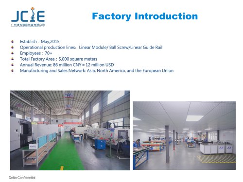 factory introduction 2024
20 Pages
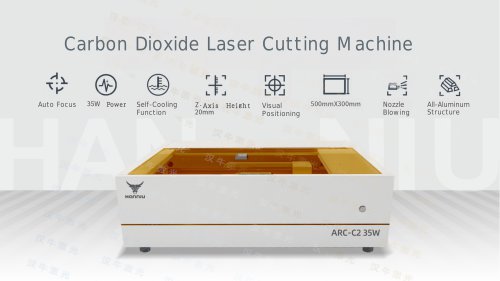
- Cutting system
- Metal cut-off machine
- CNC cutting center
- Laser cutting machine
- Sheet metal cutting machine
- Double-acting cylinder
- Plastic cutting machine
- Fiber laser cutting machine
- Precision cut-off machine
- Stainless steel cutting system
- Sheet cutting machine
- Single-acting cylinder
- Cutting system with automated loading
- Carbon steel cutting machine
- Compact cylinder
- Bridge cutting machine
- Profile cutting system
- ISO cylinder
- Aluminum alloy cylinder