- Catalogs
- Grand Growth
- JTH - Ball Screw Linear Module Catalogue
- Company
- Products
- Catalogs
- News & Trends
- Exhibitions
JTH - Ball Screw Linear Module Catalogue
1 /30Pages
JTH - Ball Screw Linear Module Catalogue
1 /30Pages
Catalog excerpts
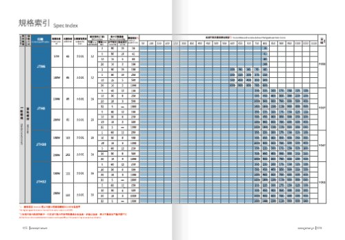
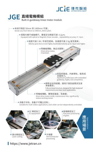
model specification The highest speed is based on the maximum servo motor’s rpm(3000). Written here is the standard storke's maximum safe speed.If over this speed,it may casue serious virbration.
Open the catalog to page 1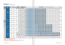
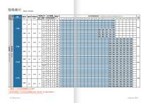
The highest speed is based on the maximum servo motor's rpm(3000). Written here is the standard storke's maximum safe speed.lf over this speed,it may casue serious virbration.
Open the catalog to page 2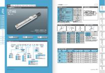
General Screw Series ^ Ball Screw Drive C MSfflil Motorside D ix,ll;iBfl!J Opposite motorside E Sensor No sensor
Open the catalog to page 3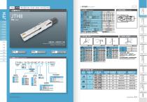
General Screw Series ^ Ball Screw Drive >snmiH Sensor layout iUStPUfll Ball screw lead mm [ AC Servo motor output Stroke pitch JS^SAiifclSSS Home sensor When the stroke is over750mm, the ai n-out of the ba llscrew wi 11 occu r. We recommend to low down the workingspeed underth is circumstances. Allowable overhang Acceleration and deacceieration value is set 02 second. ; Static Loading Moment This figure is for reference only.the shipping specifications are detailed in the dimension drawing. Maximum stroke Maximum speed The torq ue value in the chart indicate the center of gravity Operation life...
Open the catalog to page 5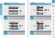
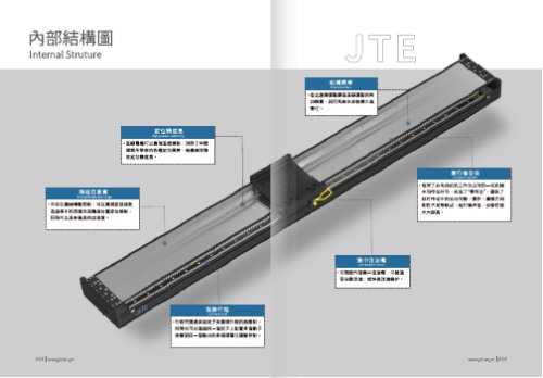
Motor exposed Motor right side
Open the catalog to page 6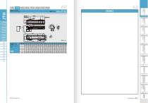
Blttsa.fi Bstfi
Open the catalog to page 7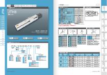
Ball Screw Drive General Screw Series Allowable overhang [ Static Loading Moment Maximum stroke Maximum speed This figure is for reference only.the shipping specifications are detailed in the dimension drawing. Vertical Installation Data information isnotforceiling-mountinverse use.Contactus forthe details ifyou wantto apply ceiling-mount inverse usage. Ball screw diameter Ball screw lead Motor position Motor brand Motor capacity Home sensor Limit sensor JSIB H^fB Brand Mark fl-StH! Out side c jsafii Motor side D EJISffiiJ Opposite motor side E Sensor No sensor ; Suitable motor brand Brake Motor...
Open the catalog to page 8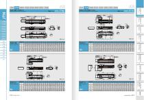
Motor left side Motor bottom side
Open the catalog to page 9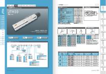
Genera Screw Series ymwmm Ball Screw Drive others Repeatability Motor capacity Home sensor Limit sensor fl-gfii Outside ftSHS Out side JSBtii Motor side sjsatt Opposite motor side ^ —Hi!i Suitable motor brand jmi mmzyt mmmmmmnm hsj^is Brand Mark Brake Watt AC-Voltage Motor model Driver model =#
Open the catalog to page 10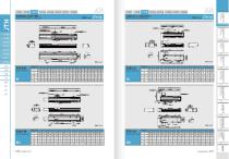
HMffiM/JigflJlBC Motor hidden in M/Motor exposed BC JH^EtfrBL/JI^&J/TBR Motor left BL/Motor right side BR
Open the catalog to page 11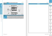
^TFUtBM Motor bottom side BM JTH10 NEMO jcIe rmaisiicsBSRcs
Open the catalog to page 12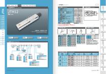
|5:§U Ball Screw Drive General Screw Series Sensor layout f&BSICflllsI Repeatability
Open the catalog to page 13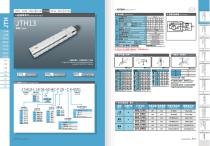
General Screw Series
Open the catalog to page 15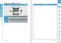
Motor bottom side BM Motor bottom side *»gs
Open the catalog to page 17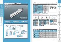
^ Ball Screw Drive jc2e fflmm. General screw Series JTH14 Maximum stroke Maximum speed This figure is for reference only.the shipping specifications are detailed in the dimension drawing. 2000m m/s 15*12.5-2^ ^ Ordering method JTH14-L16 05-50-BC-P 20 - C 4-0001■JJ Model Ball screw diameter C J|j8tl!l Motor side D * SHU Opposite motorside
Open the catalog to page 18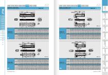
Motor hidden in M/Motor exposed BC JTH14 JI^£#TBUI^&tfrBRMotor left BL/Motor right side BR H$4/l-axis Motor left side Motor exposed Motor right side
Open the catalog to page 19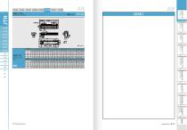
JClE HinfiBKHRiRCa Motor bottom side BM Motor bottom side
Open the catalog to page 20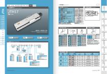
I General Screw Series Maximum stroke This figure is for reference only.the shipping specifications are detailed in the dimension drawing. Maximum speed Acceleration and deacceleration value is set 0.2 second. > mtffnmtimm Allowable overhang (HftUnitmm) ; Static Loading Moment The torque value in the chart indicate the center of gravity Operation life is 10,000km when the product is using underthe specified conditions. Data information is notlbrceiling-mount inverse use.Contactus forthe details if you want to apply ceiling-mount inverse usage. > mmmmm-nm Suitable motor brand Brand Mark Brake...
Open the catalog to page 21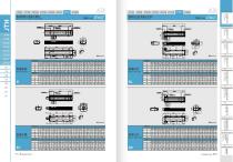
jcIe riflneHicansKcs Motor hidden in M/Motor exposed BC JTH17 Motor left BL/Motor right side BR Motor left side
Open the catalog to page 22
Motor bottom side BM Motor bottom side (Si-feu nifcmm)
Open the catalog to page 23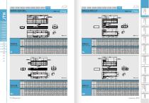
Motor hidden in M/Motor exposed BC i JTH22 Motor left BL/Motor right side BR Motor exposed 077 | www.jetran.cn Motor leftside Motor right side
Open the catalog to page 25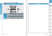
Motor bottom side BM jcle rinntSBESHHIRCB Motor bottom side
Open the catalog to page 26
ffigmis&Kn Warranty JCIE robots are designed and manufactured to be free from defects in materials and workmanship. However,should any failure occur in the robot you purchaesd, the JCIE warranty coverage is as follows. This warranty will not apply in the following cases : Warranty Period This warranty is effective for a period of: % 12 months (one and a half years) after shipment from Taiwan factory,or % 2,500 hours of actual operation whichever comes first. % Fatigue arising due to the passage of time, natural wear and tear occurring during operation (natural fading of panited or plated surfaces,...
Open the catalog to page 27
Measring Tools i. tH8?fTis/«ns Parallelism Testing / Height Testing. Measuring Tools: Dial Gauge N Dial Indicator Measuring Methods: 1. IMaB£ft£N£± Fix the actuator on granite. 2. KBJIHSftUUlM Fix the measuring tools on the actuator's slider. 2. Absolute Straightness Accuracy Testing Measuring Tools: Laser Interferometer Detection Measuring Methods: 1. l«ABCft«N:B± Fix the actuator on granite. 2. il«9B£K9ia99 Fix the measuring tools on the actuator's slider. 3. SnflSJn 77 3Ml!l is photo display. 4. ae5ijEniiju®£ Print the test report as a recoder. Belt Tension Testing Measuring Tools: fiffOMBMI...
Open the catalog to page 28
Actual value. mmmmsm • mdmmmmmmmm' ppisshshs ffijtgum m ■ - juumpii ■ • Specified Travel Specified travel. This value is determined by customer and maker as it depends on different application Specify The Target Value requirements. JMftSVS Cumulative Representative Lead Error Accumulated reference lead deviation. This is allowable deviation of specified travel. It is decided by both of the accuracy grade and effective thread length. Change Total relative lead variation Maximum width of variation over the travel length. Lead deviation in random 300 mm. smmmmnm Ball Scerw Intormation Lead Accuracy...
Open the catalog to page 29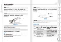
Linear Guideway Information M CD Accuracy Standard HSHFK Preload and Stiffness The accuracy of linear guideway includes the dimensional tolerance of height, width, and the running accuracy of the carriage on the rail. The standard of the dimension difference is built for two or more carriages on a rail or a number of rails are used on the same plane. The accuracy of linear guideway is divided into 5 classes, normal grade (N), high precision (H), precision (P), super precision (SP), and ultra precision (UP). The rigidity of a linear guideway could be enhanced by increasing the preload. As shown...
Open the catalog to page 30All Grand Growth catalogs and technical brochures
 Laser engraving machine B2-430
14 Pages
 JGE&JCH&JTE
10 Pages
 DC linear motor JTE23
185 Pages
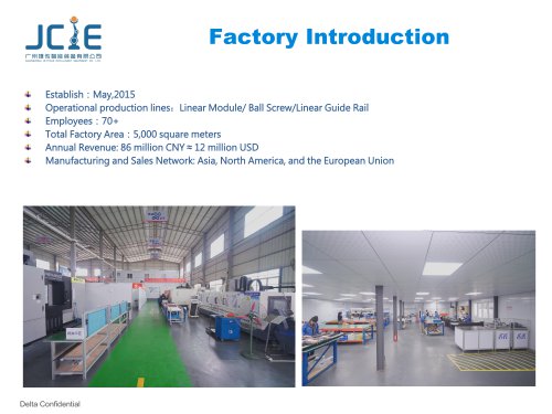 factory introduction 2024
20 Pages


- Cutting system
- Metal cut-off machine
- Cylinder
- CNC cutting center
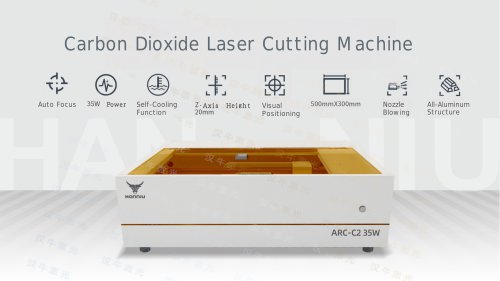
- Laser cutting machine
- Sheet metal cutting machine
- Double-acting cylinder
- Plastic cutting machine
- Fiber laser cutting machine
- Precision cut-off machine
- Stainless steel cutting system
- Sheet cutting machine
- Single-acting cylinder
- Cutting system with automated loading
- Carbon steel cutting machine
- Compact cylinder
- Bridge cutting machine
- Profile cutting system
- ISO cylinder
- Aluminum alloy cylinder