
- Catalogs
- Grand Growth
- DC linear motor JTE23


- Company
- Products
- Catalogs
- News & Trends
- Exhibitions
DC linear motor JTE23
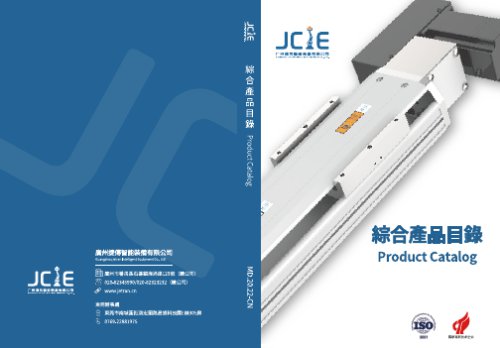
DC linear motor JTE23
Overview
This document details the technical specifications, ordering methods, installation guidelines, and operational recommendations for built-in guideway ball screw actuators and embedded electric cylinders, covering models JTG5, JTG8, JTG12, JTG15, JTY5, and JTY8. These actuators are designed for precise single-axis linear motion with integrated ball screws and guide rails, compatible with various AC servo motors.
1. Specifications
- Stroke Lengths: Ranges from 50 mm up to 1250 mm depending on model and configuration, with increments typically of 50 mm.
- Maximum Speed: Up to 2000 mm/s for larger models (JTG12, JTG15), and 1000 mm/s for smaller models (JTG5, JTG8, JTY5, JTY8).
- Motor Output Power: From 100W to 750W depending on model and motor brand.
- Ball Screw Diameter and Lead: Diameters vary from 12 mm to 20 mm; lead options include 2, 5, 10, 20, 32, and 40 mm.
- Repeatability: ±0.01 mm to ±0.05 mm depending on model and configuration.
- Acceleration/Deceleration: Preset at 0.2 seconds for optimal performance.
- Rated Thrust and Load Capacities: Vary by model, lead, and installation orientation; detailed load and moment tables are provided.
2. Ordering Method
Model numbers encode key parameters including:
- Base model (e.g., JTG5, JTY8)
- Ball screw diameter and lead
- Stroke length (increments of 50 mm)
- Motor position: motor exposed (BC), bottom (BM), left (BL), or right (BR)
- Motor brand and capacity (Mitsubishi, Panasonic, Yaskawa, Delta, Huichuan, Hechuan)
- Sensor options: home sensor and limit sensors with configurable quantity and mounting positions
- Special customizations if applicable
3. Motor and Drive Compatibility
- Supports multiple AC servo motor brands with specified motor and driver models.
- Brake options available: no brake for horizontal installation, brake-equipped for vertical installation.
- Motor shaft diameters vary by brand and power rating (e.g., Panasonic 200W motors have 11 mm shafts; others use 14 mm).
4. Installation and Load Capacity
- Installation types supported: horizontal, wall-mounted, vertical.
- Allowable overhang loads and static loading moments (MY, MP, MR) are detailed in tables, critical for mechanical design and actuator longevity.
- Payload capacities vary by model and motor power.
- Anti-rotating accuracy is ±0°, with warnings to avoid applying rotational torque to piston rods to prevent deformation and malfunction.
- For strokes exceeding 600-850 mm (depending on model), ball screw run-out (deflection) may occur; speed reduction is recommended to mitigate vibration and wear.
5. Sensors and Clean Room Options
- Home and limit sensors available with multiple mounting positions or can be omitted.
- Clean room compatible versions offered with clean screw or belt samples for contamination-sensitive environments.
6. Product Life and Usage Limitations
- Guaranteed operational life of 10,000 km under specified normal use conditions.
- Ceiling mount or inverted (upside-down) applications are not covered by standard specifications; manufacturer consultation is required.
7. Dimensions and Weights
- Detailed dimension tables provide actuator lengths (L, L1), mounting dimensions (A, M, N, P), and weights ranging from approximately 1.65 kg to over 11 kg depending on configuration.
- Motor position and stroke length directly influence overall actuator size and weight.
8. Additional Notes and Recommendations
- Acceleration and deceleration times are preset to 0.2 seconds each (0.4 seconds total).
- Use external auxiliary mechanisms for strokes over 300 mm to support radial loads and prevent ball screw run-out.
- Careful selection of motor position and lead is essential to meet space constraints and performance requirements.
- Avoid applying rotational torque to piston rods to maintain actuator integrity and sensor accuracy.
Summary
The JTG and JTY series built-in guideway ball screw actuators provide versatile, precise linear motion solutions with multiple motor, stroke, and sensor configurations. Adherence to specified load limits, stroke lengths, and installation orientations is critical to ensure optimal performance and longevity. The comprehensive ordering system allows customization to fit diverse application needs, while clean room compatible options expand usability in sensitive environments.
Catalog excerpts
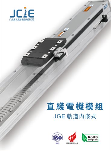
Guangzhou jetran Intelligent Equipment Co., Ltd JCiE ^0 Ittl □□ HE §§ Product Catalog MD.20.22-CN
Open the catalog to page 1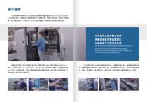
nmsmim®. > ■ as/sammi . ajixamfli J.XEi6SgJ3M1i*&seJ Advanced factory automation technology Continue to assist society and industry evolution Strive to exceed customer needs > &raibi!£tt?it£' ttransiiftttB - iiiiiiistti^ - > mmm- «agHi£iratt
Open the catalog to page 3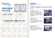
±msmm PRODUCTION AND TECHNOLOGY □nSlIfi: (QUALITY) S#“JCIE”MSS# “»/!>” Btt£' if pnpflJi^1»-JXS£ift^i>Mlii ; m > ^impnpMKi^^PW^ > ftftSJSffiflSJ* HJ^RrUK (response)
Open the catalog to page 4
Technical service and timeliness Calculation and verification tools fflftttMII Special testing report Lifetime service and maintenance Quality assurance ^»A2^7ES3^7E«ausfii ■ mmjiftmmgtim ■ mcmm - mm - imm.rn.mm ■ ■ mum MtTHA-^P&^^ppRpM ° fllVnnT^&IK Delivery lead time:7days
Open the catalog to page 5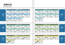
Purchase Guide Body width Maximun stroke Maximun load Maximun load Body width Maximun stroke Body width Maximun stroke Maximun load Body width Maximun stroke Body width Maximun stroke Maximun load Body width Maximun stroke RAftiS gskq Body width Maximun stroke R*ftit sokq Body width Maximun stroke Body width Maximun stroke Maximun load Maximun load Body width Body width Maximun stroke Maximun load Body width Maximun stroke Maximun load Body width Maximun stroke Maximun load Maximun stroke Maximun load Body width Maximun stroke Maximun load Body width Maximun stroke Maximun load Body width Maximun...
Open the catalog to page 6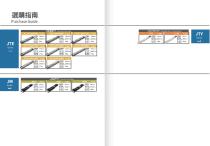
Purchase Guide Standard/Linear Motor Embedded electric cylinder series .Body width Maximun stroke ►Body width Maximun stroke Maximun load Body width Maximun stroke Maximun load Body width Maximun stroke Maximun load Body width Maximun stroke Maximun load 'Body width Maximun stroke Maximun load Body width Maximun stroke Maximun load Body width Maximun stroke Maximun load Body width Maximun stroke Maximun load
Open the catalog to page 7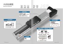
3E^!jRSia££&n ° m&wmgm sc°&p mm i tniiiipDpi ElectricSllding tableSmallersize • Optimized torque characteristics and stronger rigidity
Open the catalog to page 8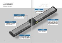
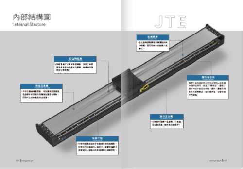
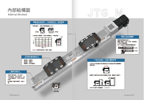
Internal Struture High precision positioning •mraRTJXJtm&m - mist*®
Open the catalog to page 9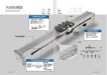
High precision embedded ball slide rail
Open the catalog to page 10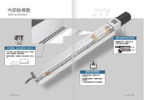
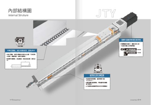
Internal Struture fifue' usm' nmnwmi ° c=o° High precision and zero rotation clearance
Open the catalog to page 11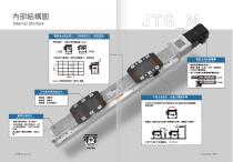
Internal Struture > pggttsa ElectricSliding tableSmaller size • Optimized torque characteristics and stronger rigidity
Open the catalog to page 12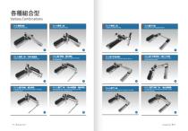
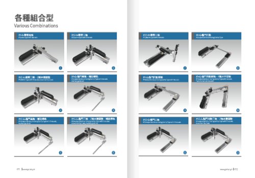
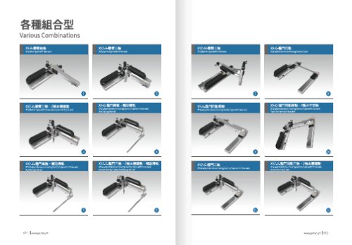
XY-A-Arm type with two axis XYZ-A-UffH^ XYZ-A-Arm type with three axis XYZ-M-HffH$i XYZ-M-Arm type with three axis XX-G-Spontaneous moving Gantry Type MZ-k-mEM ■ ZM*fl£BHi XYZ-A-Arm type with three axis,movement by Z axis xY-G-iip^$4 > XY-G-Spontaneous moving Gantry Type with two axis. Auxiliary guide rail XY-G-liP1Pi]®$4 > XY-G-Spontaneous moving Gantry Type with two axis. Y axis horizontal installatin xYz-G-mp^tt > XYZ-G-Spontaneous moving Gantry Type with three axis. Auxiliary guide rail XYZ-G-IIF1Z& . ZM*HSHl > MBmi XYZ-G-Spontaneous moving Gantry Type with three axis, movement by Z axis,...
Open the catalog to page 13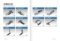
Various CombinationsXZ-F-+?M$A Cross two axis xz-f-+?®!4 > Cross two axis,Movement by Z axis xz-f-+?m$a > > 7Kw-^ ■ xz-f-+^®$4 > Cross two axis,Movement by zaixs,Horizontal installation Cross two axis,Horizontal installation XYY-G-IIP^^I^ XVY-G-Gantry combinatorial association XYYZZ-A-HimA$A XYYZZ-A-Arm type with six axis MovingArm Type with two axis MovingArmTypewiththreeaxis
Open the catalog to page 14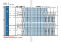
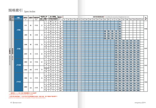
model specification The highest speed is based on the maximum servo motor’s rpm(3000). Written here is the standard storke's maximum safe speed.If over this speed,it may casue serious virbration.
Open the catalog to page 15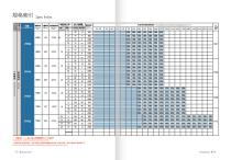
The highest speed is based on the maximum servo motor's rpm(3000). Written here is the standard storke's maximum safe speed.lf over this speed,it may casue serious virbration.
Open the catalog to page 16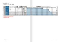
The highest speed is based on the maximum servo motor's rpm(3000). The highest speed is based on the maximum stepping motosr's rpm(500).
Open the catalog to page 17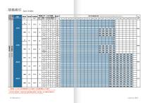
The highest speed is based on the maximum servo motor's rpm(3000) * The highest speed is based on the maximum stepping motor’s rpm(500). Written here is the standard storke's maximum safe speed. If over this speed,it may casue serious virbration.
Open the catalog to page 18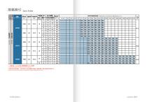
The highest speed is based on the maximum servo motor's rpm{3000). Written here is the standard storke's maximum safe speed.lf over this speed.it may casue serious virbration.
Open the catalog to page 19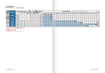
is Spec Index Clean room model specification The highest speed is based on the maximum servo motor's rpm(3000). The highest speed is based on the maximum stepping motosr’s rpm(500).
Open the catalog to page 20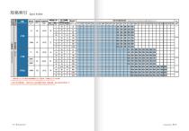
The highest speed is based on the maximum servo motor's rpm(3000),stepper motor is based on 500RPM. Written here is the standard storke's maximum safe speed.If over this speed,it may casue serious virbration.
Open the catalog to page 21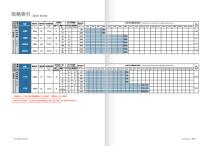
The highest speed is based on the maximum servo motor's rpm(3000),stepper motor is based on 500RPM. Written here is thestandard storke's maximum safe speed.if over this speed,it may casue serious virbration.
Open the catalog to page 22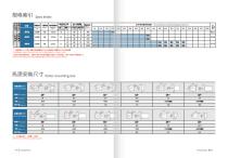
model specification Standard stroke and recommended use of the highest speed meter (mm/s) The highest speed is based on the maximum servo motor’s rprn (3000),stepper motor is based on 500RPM. Written here is the standard storke's maximum safe speed.If over this speed,it may casue serious virbration. Note:This table is for reference only, subject to actual size.
Open the catalog to page 23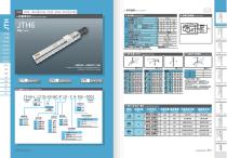
General Screw Series ^ Ball Screw Drive C MSfflil Motorside D ix,ll;iBfl!J Opposite motorside E Sensor No sensor
Open the catalog to page 24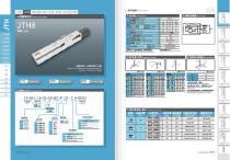
General Screw Series ^ Ball Screw Drive >snmiH Sensor layout iUStPUfll Ball screw lead mm [ AC Servo motor output Stroke pitch JS^SAiifclSSS Home sensor When the stroke is over750mm, the ai n-out of the ba llscrew wi 11 occu r. We recommend to low down the workingspeed underth is circumstances. Allowable overhang Acceleration and deacceieration value is set 02 second. ; Static Loading Moment This figure is for reference only.the shipping specifications are detailed in the dimension drawing. Maximum stroke Maximum speed The torq ue value in the chart indicate the center of gravity Operation life...
Open the catalog to page 26All Grand Growth catalogs and technical brochures
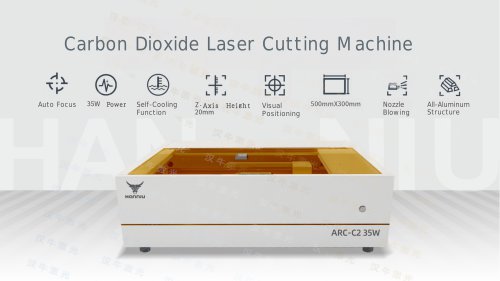
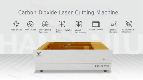 Laser engraving machine B2-430
14 Pages
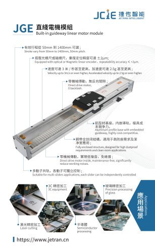 JGE&JCH&JTE
10 Pages
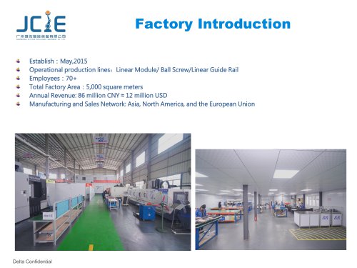 factory introduction 2024
20 Pages
- Cutting system
- Metal cut-off machine
- CNC cutting center
- Laser cutting machine
- Sheet metal cutting machine
- Double-acting cylinder
- Plastic cutting machine
- Fiber laser cutting machine
- Precision cut-off machine
- Stainless steel cutting system
- Sheet cutting machine
- Single-acting cylinder
- Cutting system with automated loading
- Carbon steel cutting machine
- Compact cylinder
- Bridge cutting machine
- Profile cutting system
- ISO cylinder
- Aluminum alloy cylinder