Manzel MBL Box Lubricator
1 /18Pages

Manzel MBL Box Lubricator
1 /18Pages
Catalog excerpts
GBL 7500 Box Lubricator Pump GBL Shaft Rotation/Low Level Alarm Pump GBL 7500 Box Lubricator Pump: Fully enclosed, self-lubricating, precision, metering pump capable of pumping small flows of either mineral or synthetic oil to machinery injection points. For professional use only. GBL Shaft Rotation/Low Level Alarm Pump: Fully enclosed, self-lubricating, precision, alarm pump capable of sensing shaft rotation and oil low level. For professional use only. 3/16” models: 7500 psi (51.7 MPa, 517 bar) Maximum Working Pressure 1/4” models: 6000 psi (41.4 MPa, 414 bar) Maximum Working Pressure 3/8” models: 3500 psi (24.1 MPa, 241 bar) Maximum Working Pressure Alarm Pump: 200 psi (1.4 MPa, 14 bar) Maximum Working Pressure Important Safety Instructions Read all warnings and instructions in this manual. Save these instructions.
Open the catalog to page 1
Warnings The following warnings are for the setup, use, grounding, maintenance, and repair of this equipment. The exclamation point symbol alerts you to a general warning and the hazard symbols refer to procedure-specific risks. When these symbols appear in the body of this manual, refer back to these Warnings. Product-specific hazard symbols and warnings not covered in this section may appear throughout the body of this manual where applicable. SKIN INJECTION HAZARD High-pressure fluid from dispensing device, hose leaks, or ruptured components will pierce skin. This may look like just a cut,...
Open the catalog to page 2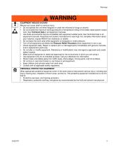
WARNING EQUIPMENT MISUSE HAZARD Misuse can cause death or serious injury. • Do not operate the unit when fatigued or under the influence of drugs or alcohol. • Do not exceed the maximum working pressure or temperature rating of the lowest rated system component. See Technical Data in all equipment manuals. • Use fluids and solvents that are compatible with equipment wetted parts. See Technical Data in all equipment manuals. Read fluid and solvent manufacturer’s warnings. For complete information about your material, request MSDS from distributor or retailer. • Do not leave the work area while...
Open the catalog to page 3
Pressure Relief Procedure Follow the Pressure Relief Procedure whenever you see this symbol. d This equipment stays pressurized until pressure is manually relieved. To help prevent serious injury from pressurized fluid, such as skin injection, splashing fluid and moving parts, follow the Pressure Relief Procedure when you stop pumping and before cleaning, checking or servicing the equipment. 1. Stop lube pump. 2. If installed, close oil supply valve located upstream from pump. 3. If installed, open drain valve located downstream from the pump. 1. Ensure the pump mounting surface on the reservoir...
Open the catalog to page 4
Setup NOTICE Any pressure applied to the pump inlet has the potential to cause unrestricted flow from the pump outlet even in a pump that is at rest or adjusted for zero stroke. To prevent this from happening, install a check valve of a comparable pressure rating at the pump outlet. NOTE: The internal “discharge check valve” does not have a spring and is rated at zero psi. a FIG. 2 b. For all installations (whether the tube needs to be trimmed or can be used without trimming), press strainer onto end of the suction tube until it “bottoms” (FIG. 3). 1. Expel all air from pump and relieve pressure...
Open the catalog to page 5
Gravity Fed Models (FIG. 5) NOTE: In the following instructions, the fill line refers to the inlet line. 1. Remove and discard the sight well plug (1) and outlet plug (5). 2. Fill the sight well (2) to the top with appropriately filtered oil. 1. Remove the sight well plug (1) and outlet plug (5). Discard outlet plug (5). 3. Operate the hand priming assembly (3) until the oil level drops below the end of the drip tube (4) (FIG. 4). 2. Fill the sight well (2) to the top with appropriately filtered oil. 4. Apply thread sealant (user supplied) to fill line fitting. 3. Operate the hand priming assembly...
Open the catalog to page 6
Alarm Pump Models (FIG. 7) 3 NOTE: In the following instructions, the fill line refers to the inlet line. 5 1 6 FIG. 6 1. Remove and discard the inlet plug (1) and outlet plug (5). 2. Apply thread sealant (user supplied) to fill line fitting. 3. Connect fill line to inlet (2). 4. Torque fill line fitting to 85 + 10 in. lbs (9.60 + 1.13 N.m). 5. If installed, open oil supply valve located upstream from the pump. 6. Operate the hand priming assembly (3) until the oil expelled from the outlet (6) if free of air. FIG. 7 1. Remove the sight well plug (1). 2. Fill the sight well (2) to the top with...
Open the catalog to page 7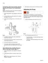
Connecting Lube Lines to Pump: Suction, Gravity and Pressure Fed Pump Models Only 3. After startup, ensure sensor is activating correctly. NOTE: The lube line refers to the outlet line supplying lubricant to the lubrication points. 1. Apply thread sealant (user supplied) to lube line fitting. 2. Connect lube line to pump outlet (6), (FIG. 8)(also see pages 15 and 16). 3. Torque lube line fitting to 50 + 5 in. lbs (5.65 + 0.6 N.m). Pump volume is controlled by an external adjusting screw (8) (FIG. 9). Turning the adjusting screw changes the length of the piston stroke which changes the pump discharge...
Open the catalog to page 8
3. For Suction Fed and Gravity Fed models only: With the lubricator operating, count the drops from the drip tube (4) falling into the sight well (2) for one minute. Calculating Output Capacity The number of drops observed falling in the sight well equals the amount of oil discharged by the pump. The pump volume can be adjusted using the adjusting screw (8) (FIG. 9) to change the piston stroke. (See Adjusting the Pump.) Calculating Pints per Day 1XPEHU RI GURSV0LQXWH Calculating Minimum or Maximum Pump Output Capacity in Pints per Day 4 2 FIG. 10 The number of drops seen falling in the sight...
Open the catalog to page 9
Specifications Table 1 Drops per Stroke Table Section of Table Applies to Suction and Gravity Fed Models Only Piston Diameter Cubic Inch/Stroke Strokes/Minute - Maximum - 50; Minimum - 3 Allowable viscosity range independent of temperature: 80-5000 SUS. Cubic cm/Stroke Stroke Length - Maximum 1/2 inch (12.7 mm) † Refer to your manufacturer’s specific instruction manuals to ensure your box and lubrication system are rated for the selected pressure. 1 Based 2 on 500 SUS oil at 70°F ambient. Heavier oil will produce fewer but larger drops. When approaching maximum outputs, some oils will stream...
Open the catalog to page 10All GRACO catalogs and technical brochures
 Pro Xp® Electrostatic Spray Guns
12 Pages
 Supply Pumps
8 Pages
 XP™ and XM Series Sprayers
28 Pages
 Triton™
8 Pages
 Fusion® CS
6 Pages
 AA G40 Automatic
4 Pages
 ToughTek® Mortar Equipment
22 Pages
 FRP Systems
16 Pages
 SaniSpray HP™
20 Pages
 PFP Sprayers
8 Pages
 Hoses, Guns and Accessories
24 Pages
 Automatic Lubrication Equipment
158 Pages
 Petroleum Handling Equipment
3 Pages
 AutoPlus™Valve
2 Pages
 Reactor
20 Pages
 FUSION™
24 Pages
 T-MAX™
3 Pages
 SDV15
SDV1512 Pages
 GL-11 Grease Injectors
2 Pages
 GL-1 Series Grease Injectors
6 Pages
 G3 Max
4 Pages
 G1 Standard
26 Pages
 SDSLBFENEU-A, Lubri-Film
7 Pages
 SDSGBLENEU-A, Box Lubricant
7 Pages
 SDSHUGENEU-A Husky Grease
9 Pages
 G1 Plus
34 Pages
 E-Series Pneumatic Pumps
2 Pages
 Manzel Model 25 Lubricator
14 Pages
 Air/Oil AO Series Valves
8 Pages
 M2K
M2K3 Pages
 Meter-Flo Pumps
4 Pages
 E-Series Lube Packages
2 Pages
 Manzel HP Lubricator
2 Pages
 Manzel® Model 25 Lubricator
8 Pages
 Force Feed Box Lubricators
16 Pages
 Manzel GBL 7500
2 Pages
 Manzel® DSL Lubricators
4 Pages
 Balancing Valve
2 Pages
 Dyna-Star 10:1
4 Pages
 GLC 4400 Multi-Purpose
2 Pages
 GLC 2200 Controller
2 Pages
 G3 Electric Lubrication Pump
8 Pages
 G1 Series Lubrication Pumps
8 Pages
 High Speed Spindl-Gard
4 Pages
 InvisiPac
8 Pages
 SaniForce Equipment Catalog
32 Pages
 Fine Finish Sprayers Brochure
13 Pages
 Graco ILE Buyer's Guide
136 Pages
 AirPro Brochure
12 Pages
 Electric Sprayers Brochure
24 Pages
 RS Resin Spray Guns
8 Pages


Archived catalogs
 High-Flo
2 Pages
 Triton 3D
2 Pages
 Reactor IP
8 Pages
 Gelcoat
8 Pages
 E-Flo
E-Flo2 Pages
 Chopper
8 Pages
 PD44 Dispensing System
8 Pages
 Style your process
2 Pages
 PCF Metering System
8 Pages
 PR70
PR7012 Pages
 MD2 Dispense Valve
2 Pages
 XTREME-DUTY™
2 Pages
 XM Plural-Component Sprayers
8 Pages
 Reactor®
12 Pages
 Process Equipment
12 Pages
 Graco’s new Hydra-CleanTM
2 Pages
 Fusion®
16 Pages
 Xtreme® Airless Sprayers
3 Pages
 Wood Finishing
140 Pages
 Paint finishing spray packages
16 Pages


- SARRALLE industrial pump
- SARRALLE electric pump
- SARRALLE stationary pump
- SARRALLE water pump
- SARRALLE self-priming pump
- SARRALLE chemical pump
- SARRALLE stainless steel pump
- SARRALLE lubricant pump
- SARRALLE dynamic mixer
- SARRALLE oil pump
- Submersible pump
- SARRALLE transfer pump
- Diaphragm pump
- SARRALLE pneumatic pump
- SARRALLE high-flow pump
- SARRALLE piston pump
- SARRALLE pressure regulator
- Food product pump