G1 Standard
1 /26Pages

G1 Standard
1 /26Pages
Catalog excerpts

G1™ Standard Lubrication Pump For dispensing of NLGI Grades #000 to #2 greases and oil with at least 40cSt. For Professional Use Only. Not approved for use in explosive atmospheres or hazardous locations. Part Nos., page 2 5100 psi (35.1 MPa, 351.6 bar) Maximum Working Pressure Important Safety Instructions Read all warnings and instructions in this manual. Save these instructions. 3132066 conforms to ANSI/UL 73 certified to CAN/CSA Std. 22.2 No 68-09
Open the catalog to page 1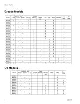
Grease Models
Open the catalog to page 2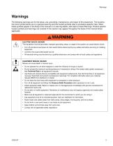
Warnings The following warnings are for the setup, use, grounding, maintenance, and repair of this equipment. The exclamation point symbol alerts you to a general warning and the hazard symbols refer to procedure-specific risks. When these symbols appear in the body of this manual or on warning labels, refer back to these Warnings. Product-specific hazard symbols and warnings not covered in this section may appear throughout the body of this manual where applicable.
Open the catalog to page 3
Grease Models with Grease Models Fig. 1: Key: A Reservoir B Pump Element C Pressure Relief Valve (Not included / required) D Zerk Inlet Fill Fitting (1 included / grease models only) E Power, DIN (if equipped) F Power, CPC (if equipped) G Low Level Output (if equipped) H Model Number/ Serial Number J Follower Plate (grease models only / not available on all grease models) K Vent Hole L Fill cap (oil models only)
Open the catalog to page 5
Typical Installation Connected to fuse / power Pressure relief valve (required, user supplied) Series progressive divider valves To lube points Choosing an Installation Location AUTOMATIC SYSTEM ACTIVATION HAZARD Unexpected activation of the system could result in serious injury, including skin injection and amputation. This device has an automatic timer that activates the pump lubrication system when power is connected or when exiting the programming function. Before you install or remove the lubrication pump from the system, disconnect and isolate all power supplies and relieve all pressure....
Open the catalog to page 6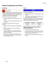
System Configuration and Wiring Fuses Grounding Improper installation of the grounding conductor may result in a risk of electric shock. This product must be installed by a qualified electrician in compliance with all state and local codes and regulations. Input Voltage If the product is permanently connected: • it must be installed by a qualified electrician or serviceman. • it must be connected to a grounded, permanent wiring system. If an attachment plug is required in the end use application: • it must be rated for the product electrical specifications. • it must be an approved, 3-wire grounding...
Open the catalog to page 7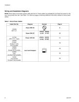
Wiring and Installation Diagrams NOTE: Graco does not provide a power cable with the G1. Power cables are available for purchase from Graco or the user may provide their own. See Table 1 for reference pages containing additional information related to Graco power cables. Table 1: Graco Power Cables
Open the catalog to page 8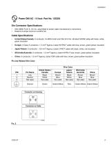
Power DIN AC - 15 foot: Part No. 123358 Din Connector Specifications • DIN 43650 Form A, 18 mm, assembled to power cable manufacturer’s instructions • Rated to 6 Amps minimum at 250V AC Cable Specifications • United States/Canada: 3 conductor 16 AWG UL62 and CSA 22.2 No. 49 listed SOOW cable with black, white, green insulation • Europe: 3 Class-5 conductor, 1.5 mm2 Agency Listed H07RN-F cable with blue, brown, green/yellow insulation • Japan/Taiwan: 3 conductor, 1.25 mm2 Agency Listed 2 PNCT cable with black, white, red insulation • SEA/India/Australia: 3 conductor, 1.5 mm2 Agency Listed H07RN-F...
Open the catalog to page 9
Installation — z-Z-Z Power DIN DC-15 foot: Part No. 123358 12VDC 24VDC Din Connector Specifications • DIN 43650 Form A, 18 mm assembled to power cable manufacturer’s instructions • Rated to 6 Amps minimum at 250V AC Cable Specifications • United States/Canada: 3 conductor 16 AWG UL62 and CSA 22.2 No. 49 listed SOOW cable with black, white, green insulation • Europe: 3 Class-5 conductor, 1.5 mm2 Agency Listed H07RN-F cable with blue, brown, green/yellow insulation • Japan/Taiwan: 3 conductor, 1/25 mm2 Agency Listed 2 PNCT cable with black, white, red insulation • SEA/India/Australia: 3 conductor,...
Open the catalog to page 10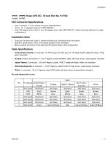
= Z"Z"Z Power CPC DC-15 foot: Part No. 127783 12 VDC 24 VDC CPC Connector Specifications • One, 7-position, 1.5 mm socket connector AMP 967650-1 • Three, 16 - 14 gauge female pins AMP 962999-1 • One, 180-degree strain relief or one, 90-degree strain relief AMP 965576-1 (determined by cable exit for cable configuration) Installation Notes • Crimp pins to wire and install in socket connector per manufacturer’s instructions. • See Pin Layout shown in Fig. 5 for proper location in the connector. • Secure socket connector to the cable per the desired strain relief configuration. Cable Specifications...
Open the catalog to page 11
Part No. 124300: Field Wireable Pin Out (M12) (Fig. 7) Wire Colors Part No. 124594: 4 Pin Eurofast Field Wireable Connector (Fig. 8) Part No. 124595: 5 Pin Eurofast Field Wireable Connector (Fig. 9)
Open the catalog to page 12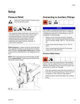
Setup Pressure Relief Connecting to Auxiliary Fittings Follow the Pressure Relief Procedure whenever you see this symbol. This equipment stays pressurized until pressure is manually relieved. To help prevent serious injury from pressurized fluid, such as skin injection, splashing fluid and moving parts, follow the Pressure Relief Procedure when you stop dispensing and before cleaning, checking, or servicing the equipment. Do not attach unsupported equipment to auxiliary fittings such as fill ports and pump element. Attaching unsupported equipment to these fitting can result in irreparable housing...
Open the catalog to page 13
Loading Grease 3. Fill reservoir with NLGI grease to max fill line. To ensure optimal performance from the G1: NOTE: Vent port, located in rear of reservoir, should not be used as an overfill port/indicator. Only use NLGI #000 - #2 greases appropriate for your application, automatic dispensing, and the equipment’s operating temperature. Consult with machine and lube manufacturer for details. The reservoir can be filled using a hand operated pump, pneumatic pump or electric transfer pump. Do not operate G1 without reservoir attached. max fill line Always clean fitting (37) with a clean dry cloth...
Open the catalog to page 14All GRACO catalogs and technical brochures
 Pro Xp® Electrostatic Spray Guns
12 Pages
 Supply Pumps
8 Pages
 XP™ and XM Series Sprayers
28 Pages
 Triton™
8 Pages
 Fusion® CS
6 Pages
 AA G40 Automatic
4 Pages
 ToughTek® Mortar Equipment
22 Pages
 FRP Systems
16 Pages
 SaniSpray HP™
20 Pages
 PFP Sprayers
8 Pages
 Hoses, Guns and Accessories
24 Pages
 Automatic Lubrication Equipment
158 Pages
 Petroleum Handling Equipment
3 Pages
 AutoPlus™Valve
2 Pages
 Reactor
20 Pages
 FUSION™
24 Pages
 T-MAX™
3 Pages
 SDV15
SDV1512 Pages
 GL-11 Grease Injectors
2 Pages
 GL-1 Series Grease Injectors
6 Pages
 G3 Max
4 Pages
 SDSLBFENEU-A, Lubri-Film
7 Pages
 SDSGBLENEU-A, Box Lubricant
7 Pages
 SDSHUGENEU-A Husky Grease
9 Pages
 G1 Plus
34 Pages
 E-Series Pneumatic Pumps
2 Pages
 Manzel Model 25 Lubricator
14 Pages
 Manzel MBL Box Lubricator
18 Pages
 Air/Oil AO Series Valves
8 Pages
 M2K
M2K3 Pages
 Meter-Flo Pumps
4 Pages
 E-Series Lube Packages
2 Pages
 Manzel HP Lubricator
2 Pages
 Manzel® Model 25 Lubricator
8 Pages
 Force Feed Box Lubricators
16 Pages
 Manzel GBL 7500
2 Pages
 Manzel® DSL Lubricators
4 Pages
 Balancing Valve
2 Pages
 Dyna-Star 10:1
4 Pages
 GLC 4400 Multi-Purpose
2 Pages
 GLC 2200 Controller
2 Pages
 G3 Electric Lubrication Pump
8 Pages
 G1 Series Lubrication Pumps
8 Pages
 High Speed Spindl-Gard
4 Pages
 InvisiPac
8 Pages
 SaniForce Equipment Catalog
32 Pages
 Fine Finish Sprayers Brochure
13 Pages
 Graco ILE Buyer's Guide
136 Pages
 AirPro Brochure
12 Pages
 Electric Sprayers Brochure
24 Pages
 RS Resin Spray Guns
8 Pages


Archived catalogs
 High-Flo
2 Pages
 Triton 3D
2 Pages
 Reactor IP
8 Pages
 Gelcoat
8 Pages
 E-Flo
E-Flo2 Pages
 Chopper
8 Pages
 PD44 Dispensing System
8 Pages
 Style your process
2 Pages
 PCF Metering System
8 Pages
 PR70
PR7012 Pages
 MD2 Dispense Valve
2 Pages
 XTREME-DUTY™
2 Pages
 XM Plural-Component Sprayers
8 Pages
 Reactor®
12 Pages
 Process Equipment
12 Pages
 Graco’s new Hydra-CleanTM
2 Pages
 Fusion®
16 Pages
 Xtreme® Airless Sprayers
3 Pages
 Wood Finishing
140 Pages
 Paint finishing spray packages
16 Pages


- SARRALLE industrial pump
- SARRALLE electric pump
- SARRALLE stationary pump
- SARRALLE water pump
- SARRALLE self-priming pump
- SARRALLE chemical pump
- SARRALLE stainless steel pump
- SARRALLE lubricant pump
- SARRALLE dynamic mixer
- SARRALLE oil pump
- Submersible pump
- Diaphragm pump
- SARRALLE high-flow pump
- SARRALLE piston pump
- SARRALLE pressure regulator
- Food product pump
- Metering pump