G1 Plus
1 /34Pages

G1 Plus
1 /34Pages
Catalog excerpts

G1™ Plus Lubrication Pump For dispensing of NLGI Grades #000 to #2 greases and oil with at least 40cSt. For Professional Use Only. Not approved for use in explosive atmospheres or hazardous locations. Part Nos., page 3 5100 psi (35.1 MPa, 351.6 bar) Maximum Working Pressure Important Safety Instructions Read all warnings and instructions in this manual. Save these instructions. 3132066 conforms to ANSI/UL 73 certified to CAN/CSA
Open the catalog to page 1
Table of Contents Grease Models . . . . . . . . . . . . . . . . . . . . . . . . . . . . . 3 Oil Models . . . . . . . . . . . . . . . . . . . . . . . . . . . . . . . . 4 Warnings . . . . . . . . . . . . . . . . . . . . . . . . . . . . . . . . . 5 Installation . . . . . . . . . . . . . . . . . . . . . . . . . . . . . . . . 7 Grounding . . . . . . . . . . . . . . . . . . . . . . . . . . . 7 Component Identification . . . . . . . . . . . . . . . 7 Typical Installation . . . . . . . . . . . . . . . . . . . . . . . . 8 Choosing an Installation Location . . . . . . . . . . . . 8 System Configuration...
Open the catalog to page 2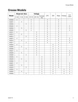
Grease Models Grease Models Reservoir Size Model 94G000 100-240 2 Liter 4 Liter 8 Liter 12V DC 24V DC VAC X
Open the catalog to page 3
Oil Models Reservoir Size Model 94G030 100-240 2 Liter 4 Liter 8 Liter 12V DC 24V DC VAC X
Open the catalog to page 4
Warnings The following warnings are for the setup, use, grounding, maintenance, and repair of this equipment. The exclamation point symbol alerts you to a general warning and the hazard symbols refer to procedure-specific risks. When these symbols appear in the body of this manual or on warning labels, refer back to these Warnings. Product-specific hazard symbols and warnings not covered in this section may appear throughout the body of this manual where applicable. WARNING ELECTRIC SHOCK HAZARD This equipment must be grounded. Improper grounding, setup, or usage of the system can cause electric...
Open the catalog to page 5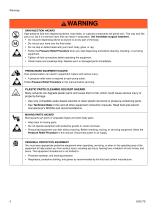
WARNING SKIN INJECTION HAZARD High-pressure fluid from dispensing device, hose leaks, or ruptured components will pierce skin. This may look like just a cut, but it is a serious injury that can result in amputation. Get immediate surgical treatment. • Do not point dispensing device at anyone or at any part of the body. • Do not put your hand over the fluid outlet. • Do not stop or deflect leaks with your hand, body, glove, or rag. • Follow the Pressure Relief Procedure when you stop dispensing and before cleaning, checking, or servicing equipment. • Tighten all fluid connections before operating...
Open the catalog to page 6
Installation Grounding The equipment must be grounded. Grounding reduces the risk of electric shock by providing an escape wire for the electrical current in the event of malfunction or breakdown. Grease Models Grease Models with Follower Plate Reservoir Pump Element Pressure Relief Valve (Not included / required) Zerk Inlet Fill Fitting (1 included / grease models only) Power, DIN (if equipped) Power, CPC (if equipped) Model Number/ Serial Number Follower Plate (grease models only / not available on all grease models) Vent Hole Fill cap (oil models only) Control Panel
Open the catalog to page 7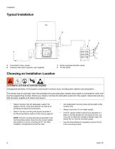
Typical Installation Connected to fuse / power Pressure relief valve (required, user supplied) Series progressive divider valves To lube points Choosing an Installation Location AUTOMATIC SYSTEM ACTIVATION HAZARD Unexpected activation of the system could result in serious injury, including skin injection and amputation. This device has an automatic timer that activates the pump lubrication system when power is connected or when exiting the programming function. Before you install or remove the lubrication pump from the system, disconnect and isolate all power supplies and relieve all pressure....
Open the catalog to page 8
System Configuration and Wiring when repair or replacement of the power cord or plug is required, do not connect the grounding wire to either flat blade terminal. Improper installation of the grounding conductor may result in a risk of electric shock. This product must be installed by a qualified electrician in compliance with all state and local codes and regulations. If the product is permanently connected: • it must be installed by a qualified electrician or serviceman. it must be connected to a grounded, permanent wiring system. NOTICE Fuses (user supplied) are required on all DC models....
Open the catalog to page 9
Power DIN AC - 15 foot: Part No. 123358 Din Connector Specifications • • DIN 43650 Form A, 18 mm, assembled to power cable manufacturer’s instructions Rated to 6 Amps minimum at 250V AC Cable Specifications • United States/Canada: 3 conductor 16 AWG UL62 and CSA 22.2 No. 49 listed SOOW cable with black, white, green insulation Europe: 3 Class-5 conductor, 1.5 mm2 Agency Listed H07RN-F cable with blue, brown, green/yellow insulation Japan/Taiwan: 3 conductor, 1.25 mm2 Agency Listed 2 PNCT cable with black, white, red insulation SEA/India/Australia: 3 conductor, 1.5 mm2 Agency Listed H07RN-F blue,...
Open the catalog to page 10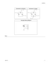
Example Wiring Diagram
Open the catalog to page 11
Power DIN DC - 15 foot: Part No. 123358 NOTICE Be sure when power is applied that stirring paddle rotates clockwise (when viewed from the top). If it is wired incorrectly paddle could rotate counter-clockwise which will damage the pump’s internal components. If this happens, stop the pump immediately and wire unit correctly. DIN 43650 Form A, 18 mm assembled to power cable manufacturer’s instructions Rated to 6 Amps minimum at 250V AC Cable Specifications • United States/Canada: 3 conductor 16 AWG UL62 and CSA 22.2 No. 49 listed SOOW cable with black, white, green insulation Europe: 3 Class-5...
Open the catalog to page 12
Example Wiring Diagram Ignition Switch
Open the catalog to page 13
Power CPC DC - 3-Wire, 15 foot: Part No. 127783 CPC Connector Specifications • • • One, 7-position, 1.5 mm socket connector AMP 967650-1 Three, 16 - 14 gauge female pins AMP 962999-1 One, 180-degree strain relief or one, 90-degree strain relief AMP 965576-1 (determined by cable exit for cable configuration) Installation Notes • • • Crimp pins to wire and install in socket connector per manufacturer’s instructions. See Pin Layout shown in FIG. 4 for proper location in the connector. Secure socket connector to the cable per the desired strain relief configuration. Cable Specifications • United...
Open the catalog to page 14All GRACO catalogs and technical brochures
 Pro Xp® Electrostatic Spray Guns
12 Pages
 Supply Pumps
8 Pages
 XP™ and XM Series Sprayers
28 Pages
 Triton™
8 Pages
 Fusion® CS
6 Pages
 AA G40 Automatic
4 Pages
 ToughTek® Mortar Equipment
22 Pages
 FRP Systems
16 Pages
 SaniSpray HP™
20 Pages
 PFP Sprayers
8 Pages
 Hoses, Guns and Accessories
24 Pages
 Automatic Lubrication Equipment
158 Pages
 Petroleum Handling Equipment
3 Pages
 AutoPlus™Valve
2 Pages
 Reactor
20 Pages
 FUSION™
24 Pages
 T-MAX™
3 Pages
 SDV15
SDV1512 Pages
 GL-11 Grease Injectors
2 Pages
 GL-1 Series Grease Injectors
6 Pages
 G3 Max
4 Pages
 G1 Standard
26 Pages
 SDSLBFENEU-A, Lubri-Film
7 Pages
 SDSGBLENEU-A, Box Lubricant
7 Pages
 SDSHUGENEU-A Husky Grease
9 Pages
 E-Series Pneumatic Pumps
2 Pages
 Manzel Model 25 Lubricator
14 Pages
 Manzel MBL Box Lubricator
18 Pages
 Air/Oil AO Series Valves
8 Pages
 M2K
M2K3 Pages
 Meter-Flo Pumps
4 Pages
 E-Series Lube Packages
2 Pages
 Manzel HP Lubricator
2 Pages
 Manzel® Model 25 Lubricator
8 Pages
 Force Feed Box Lubricators
16 Pages
 Manzel GBL 7500
2 Pages
 Manzel® DSL Lubricators
4 Pages
 Balancing Valve
2 Pages
 Dyna-Star 10:1
4 Pages
 GLC 4400 Multi-Purpose
2 Pages
 GLC 2200 Controller
2 Pages
 G3 Electric Lubrication Pump
8 Pages
 G1 Series Lubrication Pumps
8 Pages
 High Speed Spindl-Gard
4 Pages
 InvisiPac
8 Pages
 SaniForce Equipment Catalog
32 Pages
 Fine Finish Sprayers Brochure
13 Pages
 Graco ILE Buyer's Guide
136 Pages
 AirPro Brochure
12 Pages
 Electric Sprayers Brochure
24 Pages
 RS Resin Spray Guns
8 Pages


Archived catalogs
 High-Flo
2 Pages
 Triton 3D
2 Pages
 Reactor IP
8 Pages
 Gelcoat
8 Pages
 E-Flo
E-Flo2 Pages
 Chopper
8 Pages
 PD44 Dispensing System
8 Pages
 Style your process
2 Pages
 PCF Metering System
8 Pages
 PR70
PR7012 Pages
 MD2 Dispense Valve
2 Pages
 XTREME-DUTY™
2 Pages
 XM Plural-Component Sprayers
8 Pages
 Reactor®
12 Pages
 Process Equipment
12 Pages
 Graco’s new Hydra-CleanTM
2 Pages
 Fusion®
16 Pages
 Xtreme® Airless Sprayers
3 Pages
 Wood Finishing
140 Pages
 Paint finishing spray packages
16 Pages


- SARRALLE industrial pump
- SARRALLE electric pump
- SARRALLE stationary pump
- SARRALLE water pump
- SARRALLE self-priming pump
- SARRALLE chemical pump
- SARRALLE stainless steel pump
- SARRALLE lubricant pump
- SARRALLE dynamic mixer
- SARRALLE oil pump
- Submersible pump
- SARRALLE transfer pump
- Diaphragm pump
- SARRALLE pneumatic pump
- SARRALLE high-flow pump
- SARRALLE piston pump
- SARRALLE pressure regulator
- Food product pump
- Metering pump