
- Catalogs
- GÖTTING KG
- HG G-19321-A

HG G-19321-A
HG G-19321-A
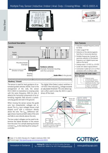
- Inductive multiple frequency sensor for AGVs, suitable for indoor use (IP 40).
- Detects electromagnetic field flux in the horizontal direction.
- Supports multiple frequencies with 8 preset options, selectable via 3 digital inputs.
- Analog output range from -10 VDC to +10 VDC.
- Guide wire detect signal available.
- Connection options include a 1.3 m cable tail or M12 connector.
- Dimensions: 98 x 67 x 34.5 mm.
- Weight: 260 g.
- Operating temperature: 0°C to +40°C; Storage temperature: -20°C to +70°C.
- Supply voltage: 24 V ±20%.
- Current consumption: approx. 100 mA.
- Protection class: IP 40.
Catalog excerpts
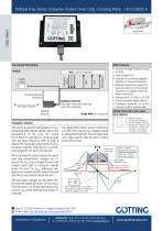
Multiple Freq. Sensor | Inductive | Indoor | Anal. Outp. | Crossing Wires Data Sheet Guide Wire Functional Description Main Features Wire detect Frequency select Inductive multiple frequency sensor for AGVs Indoor usage IP 40 Detection of the electromagnetic field (flux) in horizontal direction Multiple frequencies: 8 preset frequencies, selection of the desired frequency via 3 digital inputs (see table on the back) Analog output -10 VDC to +10 VDC Guide wire detect signal (Detect) Connection: Cable tail 1.3 m or M12 connector with or without cable Mounting bracket (example) Guidance antenna (Example: Horizontal mounting with M12 connector) Götting Product IDs (order codes) Reading distance Guide Wire (in the ground) HG G-19321ZA Production series (no functional relevance) Functional Model / Version Identification Number / Type G: Device | K: Component | S: System | W: Software HG: Götting | HW: Resale Roadway / Ground The sensor is used for track guidance of automated guided vehicles (AGVs). Due to the arrangement of the coils, the sensor HG G-19321 is insensitive to crossing wires with the same frequency. With its coils, it detects the horizontal components of an alternating magnetic field around a currentcarrying guide wire laid in the ground. When moving the sensor across the guide wire two characteristic voltages are induced. The Uref (sum voltage) shows a bell shaped curve with a maximum directly above the wire. The Upos (difference voltage) shows maxima at both sides of the wire and falls to zero directly above the wire. The two output voltages can be used to determine the lateral deviation of the sensor from the wire. For a simple steering function connect Upos to the steering drive using a Pcontroller. The digital Wire-Detect output switches to +24 VDC if the induced Uref voltage exceeds an adjustable threshold. The wire detect signal is often used to stop the AGV in case it drives off the track. Sensor with set of coils Uref (0...+10VDC) Horizontal flux strength Upos (-10...+10VDC) Vertical flux strength Wire Detect threshold (Usum) Uref Wire Detect (0/+24VDC) Magnetic flux Guide Wire For an approximately linear output the quotient of position voltage and reference voltage can be used c Date: 17.11.2023 | Revision 01 / English | Author(s): RAD / GW Product page: http://goetting-agv.com/components/19321 Götting KG, Celler Str. 5, D-31275 Lehrte, Germany Tel. +49(0)5136 / 8096-0, Fax -80, E-Mail [email protected]
Open the catalog to page 1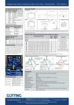
Dimensions / Mounting Pin assignment M12 connector resp. wire color of the cable tail GUTTING www.goetting-agv.com Gotting KG, Celler Str. 5, D-31275 Lehrte, Germany Tel. +49(0)5136 / 8096-0, Fax -80, E-Mail [email protected] - We reserve the right to perform modifications to our products, particularly technical improvements and further developments.
Open the catalog to page 2All GÖTTING KG catalogs and technical brochures
 HG G-76343/4/5-A
2 Pages
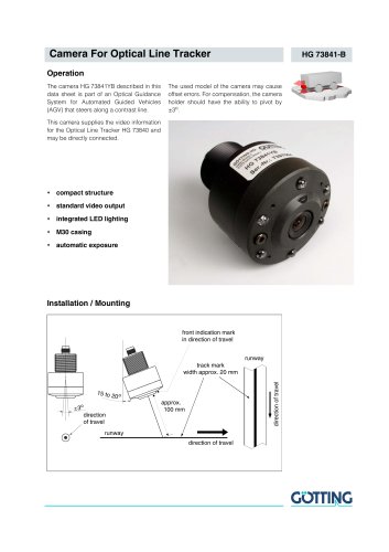 HG 73841-B
2 Pages
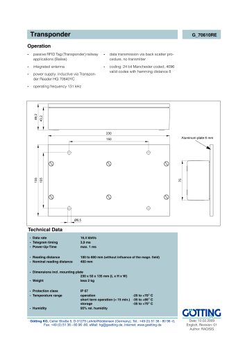 G_70610RE
1 Page
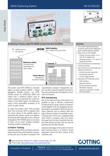 HG S-57652ZD
2 Pages
- Digital imager
- Visible imager
- Industrial camera module
- Compact imager
- Inspection imager
- Rugged camera
- Distance sensor
- Measurement scanner
- Laser scanner
- Outdoor antenna
- Magnetic sensor
- IP67 antenna
- External antenna
- Analog distance sensor
- Signal generator
- Digital distance sensor
- RS232 modem
- Vehicle antenna
- Digital control unit